In playing around with DIY electronics, Pugs has developed enough confidence to share his knowledge with his juniors. So, in one such occasion, he decided to give a try to program a micro-controller, as part of the electronics hobby club. There have been many hobbyist micro-controllers, like 8051, PIC, AVR, … and an equivalent or more varieties of hardware programmers to program them. However, Pugs’ goal was different – how can a DIY electronics learner, one as he is, do program a micro-controller in the simplest possible way with no unknown pieces of hardware, meaning no external hardware programmers. First fundamental question was if that was even possible.
“Hey Pugs, seems like it can be achieved with AVR controllers – they have a simple serial programming mechanism using their MOSI, MISO, SCK lines”, exclaimed his junior Vinay, while going through the AVR ATmega16 datasheet pg 273-277.
“Yes, seems possible, at least on the AVR side – we may just have to figure out, how to control these lines from a laptop”, asserted Pugs, reviewing the same.
“Can’t we use serial?”, ask Vinay.
“Yes, but our laptops don’t have a serial – hopefully USB to Serial converters would work”, replied Pugs.
“If it works, it would be great. We can then just connect the various serial port lines to the corresponding ATmega16 lines, and then write an application on laptop to download a ‘blink led’ program into the ATmega16”, supported Vinay.
“Regarding the application, we may not have to write one, as there is already one open source application called avrdude, specially for downloading or flashing programs into AVRs. We may just have to configure it properly”, replied Pugs.
“O! That’s good.”
“However, connecting the lines of ATmega16 to serial port may not be straight forward.”
“Why? That looks simpler than the flashing part.”
“Ya! but the challenge is that serial port lines operate on +/-12V – +12V being logic 0 and -12V being logic 1. And, micro-controllers understand 0/+5V – 0 being logic 0V and +5V being logic 1.”
“Oh! I didn’t know that there are things where 0 and 1 are not just 0V and 5V. Then, it might not be possible to connect them, right?”
“Don’t give up that easy. Where there is a problem, there would be a solution. Possibly there would be some way to do the proper voltage translations.”
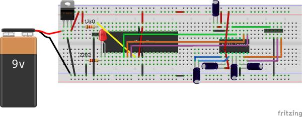
So, they explored further about the same and figured out that ICs like MAX232 are meant exactly for such purposes. MAX232 datasheet gave them the connection details. Using that, they set up the ATmega16 and MAX232 connections, as shown in the schematic and breadboard diagram below. They also connected an LED through a resistor to port pin B0 for “blink led” program. Also, they set up the reset circuitry using the pull-up resistor and the jumper J1, as reset needs to be pulled low for downloading the program into ATmega16, and needs to be set high for running the program. So, J1 would be shorted, before starting the programming, and opened for running the flashed program.

Read More: Micro-controller Programming on a Bread Board
About The Author
Ibrar Ayyub
I am an experienced technical writer holding a Master's degree in computer science from BZU Multan, Pakistan University. With a background spanning various industries, particularly in home automation and engineering, I have honed my skills in crafting clear and concise content. Proficient in leveraging infographics and diagrams, I strive to simplify complex concepts for readers. My strength lies in thorough research and presenting information in a structured and logical format.
Follow Us:LinkedinTwitter