Introduction
Our final project is a musical water fountain loosely based on the fountain in front of the famed Bellagio hotel and casino. The basic idea of the project is to take an input from an iPod (or any sound source), sample the sound and break it down to different “sequencies” by Walsh Transform , then use the output to turn on various solenoid valves. We first used a two-stage low pass filter, and then performed Fast Walsh Transforms on the sound source to split the sounds into different frequency ranges. Each different range will correspond to a different valve which comprises a musical water fountain operating to the beats and rhythms of the song.

High Level Design:
Currently, we have split the sound source into eight frequency ranges. The reasons for eight fountain heads are: 1- aesthetically appealing and 2- there are 8 pins for a standard I/O port on the Atmel Microcontroller. Since the purpose of this final project is to create a water fountain, we needed a pressurized water source. Originally, we had thought about using fish pumps; but then realized they did not have enough pressure. The pressure coming from the sink is between 30 and 40 psi, and therefore we decided to attach our input source to the sink. See below (Fig. 1) for a block diagram of our high-level design:
The entire project can be placed on a wooden stand which rests over the sink, so the water will drip back into the sink and not splash all over the area around the project. The following diagram in Fig. 2 illustrates the design of our water fountain system.
There are a few important functions we needed to implement in our project. At the start of our project, the sound source was sampled using the A/D converter on the Atmel microcontroller. From the A/D converter, the samples undergo a Walsh transform (implemented in software) to split the samples into various frequency ranges. From there the individual ranges activate the different output controls, which correspond to the opening and closing of the solenoid valves. The output controls can also activate the specific LEDs that correspond to the activated valve. In this manner, a user can both see the valves turn on and the corresponding LEDs light up. We also have pushbuttons to control the mode (single or multi) and to change the threshold.
There are a number of safety issues that we have to contend with in the implementation of our mini “Bellagio fountain”. Additionally, there are many user specifications we must also decide to minimize the safety risks. The obvious issue for our project is water damage. Most of our components cannot be mixed with water. Water will short out most of circuitry, and even cause minor electrical shock to the unlucky person standing near the project if this were to occur. We must ensure the water is separated from the electrical components with superior insulation. In order to do so, we decided to both electrically isolate the valves using the optoisolator circuit (see Fig. 4) and point the valves downward. The pressure needed to activate the valves also caused the water to shoot too high, and water was uncontrollably hitting everything around the sink when the valves were pointed upward.
Program/Hardware Design:
Software
One of the most difficult parts of our program was determining which transform we should use. Originally, we had decided to use the Fourier Transform, because we felt we understood it the best. However, the Fourier transform took too many cycles, and was not fast enough. We then had to determine whether to use the Fast Fourier transform, which splits the sound waves into different frequency ranges, or the Walsh transform. The Walsh transform is faster, and much easier to code; in fact Professor Land had already written a basic Walsh transform which we could modify for our purposes.
Unfortunately, the Walsh transform does not directly break up the sound waves into frequency ranges. Instead, it breaks up the sound waves into sequency ranges, which has a linear relationship to frequency ranges. Rather than sine and cosine, the ranges are broken into cal and sal equations. The result is often thought of as “a poor-man’s fast Fourier transform (FFT)” representing the conversion of a time-sampled signal into an equivalent frequency-sampled form. Every range has roughly 150 Hz frequency range. In the end, we chose the Walsh transform, due to its speed.
Another issue we had to deal with was how many valves should be activated at any given time. Originally, we had determined to only activate one valve at a time, due to concerns about water pressure. However, when we received Professor Land’s test code (which was designed for LEDs) multiple LEDs would turn on at any given time, and the result looked very good. We could not determine which mode was better, and so we implemented a button which would change the mode between single and multi. In single, only the sequency band with the most information would have its valve and LED activated. In multi, any sequency bands which have a content value above a certain threshold would light up.
Different songs respond better to different threshold values. If the song is a particularly muted song, a high threshold will allow no LEDs or very few to be activated. However, if the threshold is too low, all the LEDs will be activated. A default value of 40 was set for the threshold, but two buttons were implemented to allow the threshold value to be changed so all songs would be implemented correctly in our program.
For TCCR0 our prescalar is 64. This means that every 250 ticks in the program counter corresponds to one millisecond. Being that our OCR0 also equals 250, this means the program will call the interrupt compare handler every millisecond. While we check the ADC and update our Walsh transform values, we do not update the LEDs or the valve controls every millisecond. We only update these every 200 milliseconds, as the switching time for the valves would then be too much and the valves would not function properly.
Circuit
The sound source or music can be fed from any standard player (mp3, cd, walkman, pc) with the 3.5mm stereo phone jack. We used a simple 2-to-1 splitter so the music can be played through a speaker and inputted into the Analog to Digital Converter (ADC) port of the microcontroller at the same time. The sound source from a standard player (ex. mp3) can not be directly used for ADC because the output signal maximum amplitude is usually +/- 1.5 V. The input signal therefore needs to have a DC bias which eliminates negative voltages and still stay within the range of the ADC reference voltage of 5V.
Even though the audible range of a human ear is 20Hz-20kHz. We decided to sample the music at 2kHz to allow for fast ADC conversion and simple breakdown of frequency ranges. At this sampling rate, we can detect tones at up to 1kHz which will cut off high frequency treble sounds but still be useful for decoding typical music. As a result, we low pass filtered the input signal through two stages for sharper cutoff at 1kHz, removed the DC component of the sound source, and then biased the signal at 2.5V. The following Fig. 7 shows the input circuit:
We added additional functionality to our project by allowing the user to select the mode of operation for our valves and change the threshold values to produce the best pattern for the type of song playing. The three push buttons are “Mode”, “Threshold Up”, and “Threshold Down”. The default mode is set at single valve operation and the default threshold at 40. Pushing the Mode button will toggle between Single and Multi valve operation. The threshold value can range from 10-80 with a change of +/-10 depending on which button is pressed. All three push buttons have 20Kohm pull-up resistors and are soldered on to the protoboard.
The output circuits consist of the LED display and the optoisolators for the On-Off control of the eight solenoid valves. Port B of the Atmel microcontroller is used as the output controls for both the LED and the valves. The LEDs and solenoid valves are arranged in Walsh Transform sequency order. We wired the LEDs and their respective valves from lowest sequency or frequency order on the left to the highest sequency range on the right.
Since the valves are normally open, the LEDs and the valves need to turn “on” when the corresponding output pin is low. The use of inverters are needed to light the LEDs when the output is low. Optoisolators are used for each solenoid valve so they can be driven by 24V power supply and also isolate the MCU from potentially harmful inductive spikes. Fig. 9 is a circuit diagram of the output controls and LED displays.
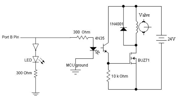
Fig. 9:Output Circuit (LED and Optoisolator)
Hardware
A three stage adapter screws into the faucet connection and reduces it to 3/8’’ ID poly tubing. This tube is then sent into a port on the back of our container. Figure 10 is a diagram showing how water is distributed to the eight valves. After the first T splitter, the tubing is reduced to 3/16’’ ID. This size is based on the adapters and splitters we were able to sample free of cost. We also felt that since the input 3/8’’ tubing is being split eight ways, reducing the tube size would help maintain water pressure, which was an ongoing concern.
The design is fairly straightforward – coming in with single tube, the water is divided using T splitters into 2, 4, and then 8 different connections. All T splitters and connections to the valves are quick connect fittings, which as the name states are much easier than using barbs and hose clamps. At first we were concerned, but the quick connect fittings are strong enough to handle our water pressure, and we had no leaks from these at any point during testing.
The valves used in our project are 3-way, which was not our original design. We originally planned on having 2-way valves, and a separate, single outlet control for the water in case all valves are off. However for these 3-way valves when a voltage is applied, any water being pumped to the input is sent out the third port. Another set of quick connect adapters is screwed into these outlet ports and connected in similar fashion to the inputs, with a separate outlet tube for each set of four valves. This system adequately handles water and prevents leaks when water is on, but all valves are turned off.
Another decision we had to make was how to secure the valves to our plastic container, ensuring that only the output tip would be outside the container. Each valve came with an adapter screwed on the top output port (see Figure 10). We decided to cut a hole in the top of the container small enough that the tip of the valve would stick through the lid. Then screwing the adapter on from the outside locks the valve into place. Eight equally spaced holes were measured and marked, and the eight valves fit in the container perfectly.
At first we were unsure how to cut the holes in the lid, since the plastic can shatter when cut. Based on a suggestion from Professor Land, we heated a nail and used it to burn the holes in the lid. After using a knife to clean up the edges, we had eight properly sized holes to secure the valves onto the lid. The benefit of this setup is that no additional adapters or tubing are needed in order to visibly shoot water from the container.
Pars List:
|
Part |
Cost |
|
Custom PC Board |
$5 |
|
Mega 32 Chip |
$8 |
|
3/8” tubing (4 ft) |
$0.92 |
|
3/8” – ¼” barb adapter |
$1.52 |
|
4 Hose Clamp |
$2.36 |
|
Solder Board |
$2.50 |
|
2 Broken Solder Boards |
Free |
|
30V Power Supply for Valve |
Free |
|
Wood & Nails |
Free |
|
Plastic Box |
Free |
|
Opto-isolators, Resistors, Capacitors, Wires, Headers |
Free |
|
Power Supply |
$5 |
|
Quick Connects for Valves |
Free |
|
T-Connects |
Free |
|
5/16” tubing |
Free |
|
Sink Adapter |
$2.27 |
|
½’’ tube connecter |
$7.72 |
|
½” tube |
$0.33 |
|
8 Skinner 3-way valves |
$6.66 |
|
TOTAL |
$42.28 |
For more detail: Musical Water Fountain Using Atmega32