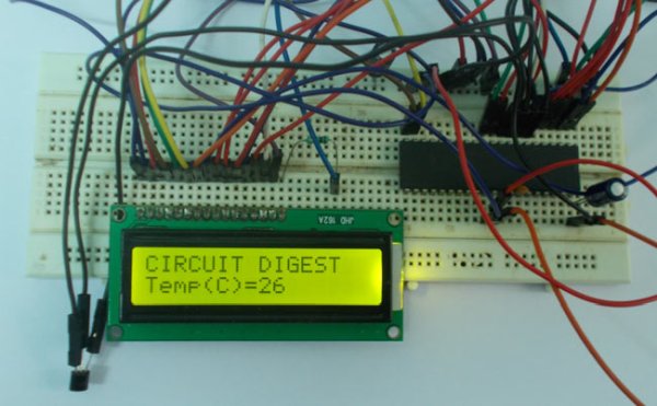
In this project we are going to design a circuit for measuring temperature. This circuit is developed using “LM35”, a linear voltage sensor. Temperature is usually measured in “Centigrade” or “Faraheite”. “LM35” sensor provides output based on scale of centigrade.
LM35 is three pin transistor like device. It has VCC, GND and OUTPUT. This sensor provides variable voltage at the output based on temperature.
As shown in above figure, for every +1 centigrade raise in temperature there will be +10mV higher output. So if the temperature is 0◦centigrade the output of sensor will be 0V, if the temperature is 10◦ centigrade the output of sensor will be +100mV, if the temperature is 25◦ centigrade the output of sensor will be +250mV.
So for now with LM35 we get temperature in the form of variable voltage. This temperature dependent voltage is given as input to ADC (Analog to Digital Converter) of ATMEGA32A. The digital value after conversion obtained is shown in the 16×2 LCD as temperature.
Components Required
Hardware: ATMEGA32 Microcontroller, power supply (5v), AVR-ISP PROGRAMMER, JHD_162ALCD (16x2LCD), 100uF capacitor (two pieces), 100nF capacitor, LM35 Temperature Sensor.
Software: Atmel studio 6.1, progisp or flash magic.
Circuit Diagram and Explanation
In the circuit, PORTB of ATMEGA32 is connected to data port of LCD. Here one should remember to disable the JTAG communication in PORTC ot ATMEGA by changing the fuse bytes, if one wants to use the PORTC as a normal communication port. In 16×2 LCD there are 16 pins over all if there is a back light, if there is no back light there will be 14 pins. One can power or leave the back light pins. Now in the 14 pins there are 8 data pins (7-14 or D0-D7), 2 power supply pins (1&2 or VSS&VDD or gnd&+5v), 3rd pin for contrast control (VEE-controls how thick the characters should be shown), 3 control pins (RS&RW&E).
In the circuit, you can observe I have only took two control pins as this give the flexibility of better understanding. The contrast bit and READ/WRITE are not often used so they can be shorted to ground. This puts LCD in highest contrast and read mode. We just need to control ENABLE and RS pins to send characters and data accordingly.
The connections which are done for LCD are given below:
PIN1 or VSS ——————ground
PIN2 or VDD or VCC————+5v power
PIN3 or VEE—————ground (gives maximum contrast best for a beginner)
PIN4 or RS (Register Selection) —————PD6 of uC
PIN5 or RW (Read/Write) —————–ground (puts LCD in read mode eases the communication for user)
PIN6 or E (Enable) ——————-PD5 of uC
PIN7 or D0—————————–PB0 of uC
PIN8 or D1—————————–PB1 of uC
PIN9 or D2—————————–PB2 of uC
PIN10 or D3—————————–PB3 of uC
PIN11 or D4—————————–PB4 of uC
PIN12 or D5—————————–PB5 of uC
PIN13 or D6—————————–PB6 of uC
PIN14 or D7—————————–PB7 of uC
In the circuit you can see we have used 8bit communication (D0-D7) however this is not a compulsory, we can use 4bit communication (D4-D7) but with 4 bit communication program becomes a bit complex so I have choosed the 8 bit communication.
So from mere observation from above table we are connecting 10 pins of LCD to controller in which 8 pins are data pins and 2 pins for control. The voltage output provided by sensor is not completely linear; it will be a noisy one. To filter out the noise a capacitor needs to be placed at the output of the sensor as shown in figure.
Before moving ahead we need to talk about ADC of ATMEGA32A. In ATMEGA32A, we can give Analog input to any of eight channels of PORTA, it doesn’t matter which channel we choose as all are same. We are going to choose channel 0 or PIN0 of PORTA. In ATMEGA32A, the ADC is of 10 bit resolution, so the controller can detect a sense a minimum change of Vref/2^10, so if the reference voltage is 5V we get a digital output increment for every 5/2^10 = 5mV. So for every 5mV increment in the input we will have a increment of one at digital output.
For more detail: Temperature Measurement using LM35 and AVR Microcontroller