Introduction
The ultrasonic haptic vision system enables a person to navigate hallways and around large objects without sight, through the use of an ultrasonic rangefinder that haptically interfaces with the user via tiny vibrating motors mounted on the users head. The idea behind this project was to construct a sixth sensory system that interacts with the body in an intuitive and user friendly fashion and enables the user to navigate without vision. We also implemented RF transmission in order to provide feedback to a program running on the computer to keep track of the sensory data obtained from the mobile user mounted sensor system. This enabled the person sitting at the computer to observe all the distances between the surrounding obstacles and the user wearing the hat. The rangefinder rotated on a motor atop the hardhat in order to take the sensory data at discrete points around the user. The hat and required hardware is all battery powered so that it is totally mobile and can be used as intended, so that movement is not restricted by the length of wires.

High Level Design
Rationale | Logical Structure | Hardware and Software Tradeoffs
Rationale and Sources
The rationale behind this project was to demonstrate an idea by creating a working prototype of a sensory system to enable the sight impaired to navigate through hallways and around large objects. We also thought that the idea of integrating all of the different hardware and using sensory hardware to actuate feedback hardware was very interesting. Putting all of this in a mobile package was no easy task but it was a great learning experience. The source of the idea behind our project was from work done by graduate students at the University of Tokyo. They created a headband with infrared sensors with vibrating motors that vibrate when an object is found within range. The module was not mobile and was linked to a PC and the range of the sensors was minimal as they were infrared. This idea spurred our interest in using a haptic feedback system to alert the user to objects at greater distance in the vicinity.
Logical Structure
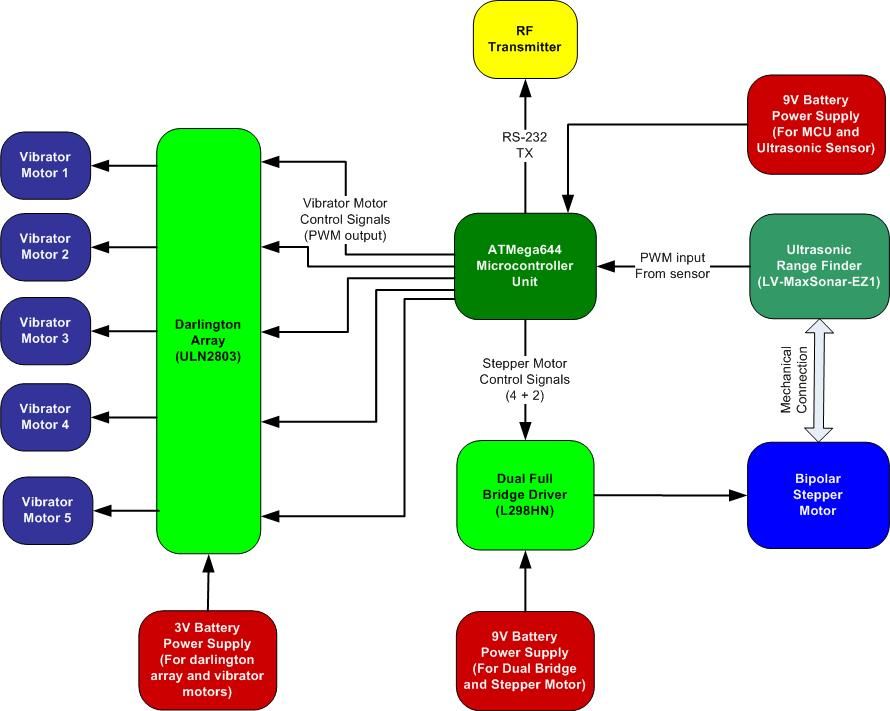
The basic logical structure of our project involves the sensory input from the ultrasonic rangefinder and its method of acquisition, the bipolar stepper motor that changes the sensor position to read ranges at different angles, the miniature vibrating motors that provides haptic feedback to the user and the microcontroller which enables the three major components to communicate effectively. We also had a base station which communicates with the mobile station via radio-frequency transmission, receives all of the hardware states and sensory information and displays it in an intuitive way for debugging and general informative display of the sensory information. The motor atop the hard hat turns the ultrasonic sensor, which reads the distance to the nearest object at different angles and sends this information to the microcontroller which in turn sets the vibrator strength in that direction accordingly, to alert the user to the distance to the nearest object in that direction. At the same time the microcontroller relays this range information at the current angle back to the base station to display it on the computer.
Hardware and Software Tradeoffs
Anything that we determined could be easily implemented in hardware or software we opted to do in software because our processor was not very taxed for computing power, to begin with. The original idea was to use a L297 Stepper Motor Controller to control the bipolar stepper motor step sequences, but we decided that this was much easier done with the microcontroller because it required less connections and we could control better the number of steps, the reversal of direction and the speed of rotation of the motor. Also, it was a better idea for us to offload the hardware onto the software because we had extra processing power and the circuitry required for this project was already significant.
Hardware Design
Ultrasonic Sensor | Full Bridge | Stepper Motor | Darlington Array | RF Circuit | Hardware Construction | Design Mistakes
The following is a brief description of some of major components that we used in our hardware design of the system. We also used some boards generously donated by Freescale to the lab in this final project. We used the DS1532 9V battery board and two small soldering boards. Unfortunately the 5V regulator on the battery board could not supply enough current to drive our stepper motor so we soldered into the board a new regulator (LM340T5) to supply the necessary power to the motor.
1. Maxbotix LV-EZ1 Ultrasonic Range Sensor
This is a very small, easy to use ultrasonic sensor that has three different types of outputs, Pulse Width Modulation, Analog, and RS-232 making it a very versatile piece of hardware. The sensor is able to read at 20 Hz and reads in inch increments from 6 to 255. The only problem with this sensor is that there are some random extreme values, either a min or a max, that are difficult to filter out because each reading is a completely different point. It is very hard to distinguish whether the sensor reading is an actual distance reading or an erratic error value because a 1D sensor is used to read ranges on a 2D plane. Thus, a sharp dip or rise in the sensor value might correspond to an actual range reading at an angle. This variations may be due to the vibrations of the motor it is mounted atop or just an intrinsic property of the sensor. It is most likely a combination of the two because the sensor was not designed for rough moving applications as we used it for. We also used it in a very noisy environment which added to the inaccuracies or fluctuations. For this project the pulse width modulation output was used because it is easy to read from the microcontroller and is a digital signal and thus is not subject to noise on the line back to the MCU. Also, with all of the noisy motors and such attached to the microcontroller, it would not have been a good idea to use the ADC because of all the noise generated.
2. L298HN Full Bridge
The L298 is a very useful dual full bridge driver that can be used to guide and control the flow of current from the attached power supply using CMOS control signals. Thus using this dual bridge, we could drive our bipolar stepper motor using control signals to any desired voltage output. We drove the bridge with a bipolar stepper motor pulse sequence generated by the microcontroller and a 5V regulated voltage rail for the power input.
3. PF35T-48L4 Bipolar Stepper Motor
PF35T-48L4 is a bipolar stepper motor that moves in increments of 7.5 degrees/step, operates at 5 Vdc and consumes about 300mA (with attached load), which is pretty small compared to other motors we tested. Another major feature about this motor was its small size and so, it was easily mounted at the top of the hard hat.
4. ULN2803 Darlington Array
This chip is an 8-pair Darlington array which was used to drive the vibrating motors from input CMOS pulses generated by the microcontroller. The output voltage is variable for the darlington pair and was set to 3V by using two AA batteries in series. Control signals were sent from the microcontroller to the darlington array to control the intensity and the operation of the vibrator motors. Thus, this chip was also used to guide the power supplied by the 2 AA batteries to the attached vibrator motors.
5. RCT-433/RCR-433, MM74C04N RF Circuitry
The RCT-433 is an RF transmitter running at 433 MHz which takes an inverted input from the MM74C04N inverter and transmits the signal over an attached antenna. The UART0 port on the microcontroller was used to send and receive RF data from the chips and since this port follows RS-232 protocol, a low represents a logical high on the input. Thus, the signal had to be inverted to correctly represent the data sent from the transmitter. The RCR-433 is the corresponding RF receiver running at 433 MHz, with the output of this chip inverted by the 04N before being input to the microcontroller. The inversion at the receiver end follows similar reasoning as above.
6. Hardware Construction
The EZ1 sensor was mounted on a small piece of wood using screws which were connected to some sort of tube through an L-bracket, we were able to scrounge in the lab. This tube was glued on top of the motor gear so that the sensor turned with the motor. A contact switch was created so that the motor would rotate or sweep through the desired angle no matter the position of the motor on start up. This was done by gluing a wire sticking up from the hat and then gluing one sticking down from the piece of wood that the sensor was mounted on which moves with the motor. This was done in such a way that the two wires are in contact in the desired starting position of the motor which was the farthest angle read in the counterclockwise direction. A sweep of -135 degrees to +135 degrees was used in our design because we intended to have 7 motors each 45 degrees away from each other. Thus, the two wires that make up the switch are in contact when the motor is at approximately -135 degrees. The motor was also mounted in the hardhat by screwing it into the top of the hat and drilling a hole in the middle for the gear to protrude from the top of the hat, so the sensor could be mounted on it. More holes were drilled in the hat so that various wires could enter and exit as cleanly as possible, and also made it a bit safer, so that everything was contained in the hat and away from the user as much as possible. The hardhat has an insert in it that keeps the users head away from the top of the hat giving us room to mount the motor in the top. The insert also has a padded front that is in contact with the users forehead. This padded front was perfect for mounted the vibrators inside because it keeps the padding between the user and the vibrators which makes it more comfortable. The weight on the top of the tiny DC motor vibrators which enables them to vibrate was out in the open, and if put in an enclosed space the motor will not turn because the weight gets stuck and thus the motor will not vibrate. To fix this, the motors were encased in hollow cylindrical pieces of aluminum which were fashioned by hand out of a sheet of aluminum. With this quick fix the motors vibrated perfectly inside of the padded insert in the hat and were simply taped in to keep them in place. All of the wires coming out of the hat were taped to keep them together and all of the wires in the hat were taped to various parts of the hat or the insert, for the vibrators, so that there were no dangling wires inside to get caught on anything. The rest of the mobile circuitry is inside of a plastic case aside from all of the necessary batteries which are taped to the outside because they are so big. Inside of the case is the mobile MCU board which is powered by a 9V battery. It also contains the motor driving circuit board which is made up of the L298 along with a few simple circuit elements and is powered by a 9V battery through the LM340T5 5V regulator and controlled by outputs from the MCU. Next in the case is the ULN2803 which powers the vibrating motors using two AA batteries in series and controlled by outputs from the MCU. Finally the case contains the RF transmitter circuitry so as to transmit the sensory data obtained from the users surroundings back to the base and ultimately a PC connected to it. This involves a board with an inverter chip and a board specifically designed to hold the RCT-433 RF transmitter module, as well as an antenna that had to stick out of the case in order for the signal to be transferred. The base station contained little circuitry, having an MCU board with a Max233 for RS-232 connections to the computer, a RCR-433 board and inverter board for receiving the RF packets from the transmitter on the mobile board and a led board to denote the current state of the vibrating motors on the hat, indicating whether they are on or off. Overall the hardware in this project took the majority of time with the mounting and testing as well as the verification that it would work as intended. Even waiting for the hardware slowed the progress of this project significantly.
7. Design Mistakes
Our initial design consisted of using piezoelectric buzzers to implement the vibrating feedback to the user, which was based on a presumption that the vibration of these would be enough to provide significant haptic feedback to the user. This idea was based on a recommendation to use these elements. Unfortunately, these turned out to not fit the application we needed them for. They mainly generated sound and were only able to vibrate a small amount, which was not nearly enough for our application. Unless we assumed the users sense of touch was super sensitive these buzzers were not going to work. Unfortunately this took us two weeks to determine because we had ordered buzzers in the first week of final projects but did not receive them for a week and a half. Thus we decided to order mini DC vibrating motors for use as the vibrating feedback in our design and ordered them in the next possible order. We decided to try a different vendor because the last one had taken a very long time, so we ordered from BG micro instead. Unfortunately this was a big mistake as the shipment did not come before the end of final projects and was thus useless. We determined that our parts would not be arriving until a few days before final projects were due, and we had finished everything else besides the vibrating feedback for a good number of days. Thus, we decided to go to RadioShack to get the motors because we needed them immediately, despite the inflated price. Unfortunately, they only had 5 motors (between Ithaca and Cortland) and not the 7 our original design called for and we had no choice but to design it with the 5 motors.
Parts List:
|
Part Name |
Manufacturer |
Part Number |
Qty |
Unit Price |
Cost |
Acquire Method |
| Ultrasonic Range Finder | Maxbotix | LV-EZ1 |
1 |
24.95 |
|
Sampled |
| Maxim dual RS232 I/F | Maxim | MAX233CPP |
1 |
7.00 |
|
Sampled |
| Mega644 microcontroller | Atmel | ATMEGA644 |
2 |
8.00 |
8.00 |
Sampled 1, Purchased 1 |
| Vibrator Motors | RadioShack | 273-107 |
5 |
0.99 |
4.95 |
Purchased |
| Stepper Motor | Jameco | 171601 |
1 |
2.95 |
2.95 |
Purchased |
| 9V Battery | Duracell |
2 |
2.00 |
4.00 |
Purchased | |
| 9V Battery Clip | Keystone Elec | 84-6k-ND |
1 |
0.57 |
0.57 |
Lab Stock |
| Small Solder Board |
3 |
1.00 |
3.00 |
Lab Stock | ||
| Freescale Solder Board | Freescale |
1 |
Free |
|
Sampled | |
| Freescale Power module | Freescale |
1 |
Free |
|
Sampled | |
| Dual Full Bridge | STMicroelec | L298HN |
1 |
4.93 |
|
Sampled |
| 5V Reg – Higher Amps | LM340-T5 |
1 |
1.00 |
1.00 |
Lab Stock | |
| Custom PC board |
2 |
4.00 |
8.00 |
Lab Stock | ||
| DIP socket |
3 |
0.50 |
1.50 |
Lab Stock | ||
| Header Pins |
24 |
0.05 |
1.20 |
Lab Stock | ||
| RS232 DB9 Connector | Tyco Elec | A2100-ND |
1 |
2.00 |
2.00 |
Lab Stock |
| RS232 Connector wire |
1 |
1.00 |
1.00 |
Lab Stock | ||
| Power Supply |
1 |
5.00 |
5.00 |
Lab Stock | ||
| RF Transmitter | Radiotronix | RCT – 433 |
1 |
4.00 |
4.00 |
Lab Stock |
| RF Receiver | Radiotronix | RCR – 433 |
1 |
4.00 |
4.00 |
Lab Stock |
| Machine Pins |
100 |
0.05 |
5.00 |
Lab Stock | ||
| Blue Hard Hat |
|
|
Owned | |||
| Materials for sensor mount |
|
|
Salvaged | |||
| Transmitter Unit Box |
|
|
Salvaged | |||
| Inverters | MM74C04N |
2 |
1.00 |
2.00 |
Lab Stock | |
| Darlington Array | T.I. | ULN2803AN |
|
|
Sampled | |
|
Total Price |
$ 58.17 |
For more detail: Ultrasonic Haptic Vision System using Atmega644