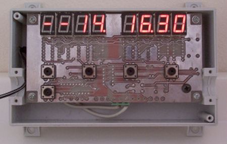
The original version of xTimer used MAX7219 for driving 7-segment. This new design uses a cheap CMOS shift register, 4094 for LED interface. Each 4094 drives a 0.5″ 7-segment without the need of limiting resistor. The left-hand LED is timer function with buzzer alarm output. The right-hand is for clock display.
Hardware Schematic
Fig. 2 shows a complete hardware schematic. U2 is ATMEL 89C2051 running with 24MHz xtal. The original version uses 11.0592MHz, this version I need the accurate clock, so I chose 24MHz. Since the clock input to timer is 24MHz/12=2MHz. To produce 100Hz timer interrupt, we can then use reload value for timer0 with 65536-20000=45536.
The input keypad for timer setting, key1 to key4 are tied to P3.2 to P3.5 using internal pull-up. P3.0 and P.3.1 drive two buzzers through 7407 buffer gate. The output is active low. Output1 to output4 are open collector. We can use them to drive small +12V relay directly.
U3,U5,U7,U9,U12,U14,U16 and U18 are CMOS shift register 4094 making the 64 bits CMOS output port. Each chip drives the 7-segmant directly. The brightness for 0.5 inches LED shows very well. Notice that the output of CMOS shift register can drive the segment without external current limiting resistors. The VOH will drop when it sources the current. This feature makes the circuit is easy to build. All 64-bit CMOS output is controlled by three signals, i.e. DATA, STROBE and CLK. The signals are generated by software controlled: DATA by P1.6, STROBE by P1.5 and CLK by P1.7.
64-bit data stream is shifted into the U3 pin2 with rising edge of CLK signal. QS is the output bit that ties to the next data input. STROBE and CLK signal are tied to each 4094 chip. When all 64-bit are complete shifted, the trailing edge of STROBE will write them to the output concurrently.
Software
The firmware is timer interrupt driven program. The interrupt rate is 100Hz. The XTAL is 24MHz. Timer0 receives 24MHz/12=2MHz. To produce 100Hz, the reload value then equal 65536-20000=45536 or 0xB1E0. Below is timer0 interrupt service function. All tasks will be executed every 10ms.
| void timer_isr(void) interrupt 1 using 1 { TH0 |= 0xb1; // reload value with 24MHz Xtal TL0 |= 0xe0; cputick++; clock(); // update realtime clock set_timer(); run_timer(); key_release(); updatedisplay(); ring1(); ring2(); } |
I have replaced timer function for timer3 and timer4 with clock. Below shows new layout. Now Key3 and Key4 can adjust current time for HOUR and MIN easily.
For more detail: xTimer with 4094 using ATMEL89C2051 microcontroller

