In this project we are going to make a low range ammeter using ATMEGA8 microcontroller. In ATMEGA8, we are going use 10bit ADC (Analog to Digital Conversion) feature to do this. Although we have few other ways to get the current parameter from a circuit, we are going to use resistive drop method, because it’s the easiest and simplest way to get current parameter.
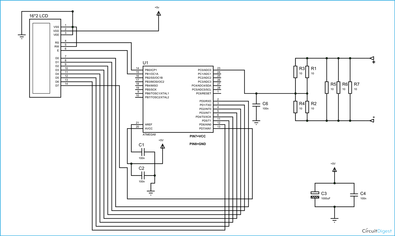
In this method we are going to pass the current which needed to be measured in to a small resistance, by this we get a drop across that resistance which is related to current flowing through it. This voltage across resistance is fed to ATMEGA8 for ADC conversion. With that we will have the current in digital value which will be displayed on a 16×2 LCD.
For that we are going to use a voltage divider circuit. We are going to fed the current through the complete resistance branch. The midpoint of branch is taken to measurement. When current changes there will be drop change in the resistance which is linear to it. So with this we have a voltage which changes with linearity.
Now important thing to note here is, the input taken by the controller for ADC conversion is as low as 50µAmp. This loading effect of resistance based voltage divider is important as the current drawn from Vout of voltage divider increases the error percentage increases, for now we need not worry about loading effect.
Components Required
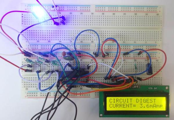
Hardware: ATMEGA8, power supply (5v), AVR-ISP PROGRAMMER, JHD_162ALCD (16*2LCD), 100uF capacitor, 100nF capacitor (4 pieces), 100Ω resistor (7 pieces) or 2.5Ω (2 pieces), 100KΩ resistor.
Software: Atmel studio 6.1, progisp or flash magic.
Circuit Diagram and Working Explanation 
[See this tutorial to understand how to interface LCD with AVR Microcontroller]
The voltage across R2 and R4 is not completely linear; it will be a noisy one. To filter out the noise, capacitors are placed across each resistor in the divider circuit as shown in figure.
In ATMEGA8, we can give Analog input to any of FOUR channels of PORTC, it doesn’t matter which channel we choose as all are same. We are going to choose channel 0 or PIN0 of PORTC. In ATMEGA8, the ADC is of 10 bit resolution, so the controller can detect a minimum change of Vref/2^10, so if the reference voltage is 5V we get a digital output increment for every 5/2^10 = 5mV. So for every 5mV increment in the input we will have a increment of one at digital output.
For more detail: 100mA Ammeter using AVR Microcontroller