
Summary of 10A 400V DC Intelligent Power Module (IPM)
Summary: A 10 A, 400 V DC Intelligent Power Module (IPM) evaluation board built around ON Semiconductor STK544UC62K integrates a 3-phase inverter output stage, gate pre-drives, bootstrap supplies, protections (UV/OV, over-current, temperature), op-amp current sensing, comparator fault output, and an onboard 5 V regulator. It supports AC induction, BLDC, PMSM, and brushed DC motors, accepts MCU 14-pin input for six PWM signals, and includes bulk caps, shunt-based current sensing, low-pass filters, and bus-voltage monitoring for VFD and motor-control development.
Parts used in the 10A 400V DC Intelligent Power Module (IPM) Board:
- ON Semiconductor STK544UC62K (Intelligent Power Module)
- Bulk capacitors
- Bootstrap capacitors (three, one per phase)
- Bootstrap Zener diodes (one per phase)
- Single shunt resistor for current sensing
- MCP6021 op-amp (current to voltage converter)
- LMV7235 comparator (Fault/Over current output)
- Onboard 5V DC regulator
- 14-pin header connector for MCU/motion-controller interface
- Six low-pass filters on gate input signals
- Resistor divider networks for bus voltage monitoring
- Resistor divider / sensing circuitry for inverter phase current
- Thermistor or internal substrate temperature sensing circuitry
- Screw terminal connectors for three-phase outputs (UU, VV, WW)
- PCB with traces and mounting for high-voltage motor up to 400V DC
10 Amp 400V DC Intelligent power module board has been designed using ON Semiconductors STK544UC62K. This Inverter IPM module includes the output stage of a 3-phase inverter, pre-drive circuits, bootstrap circuits, protection circuits, op-amp based current sense circuit, comparator circuit for fault/Over current output, Bus voltage output, onboard 5V DC regulator for op-amp circuit.
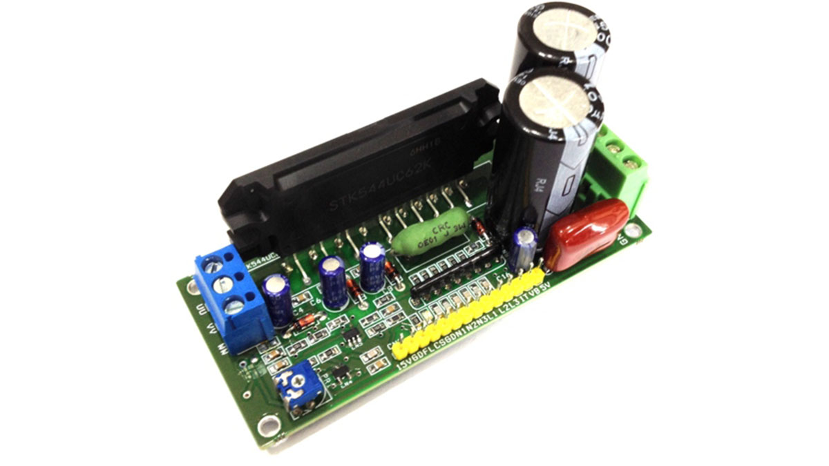
This board can be used to drive AC Induction, BLDC, PMSM motors and Brushed DC Motors. The module integrates optimized gate drive of the built-in IGBTs to minimize EMI and losses, while also providing multiple on-module protection features including under-voltage or over voltage , over-current , and fault reporting. The built-in, high-speed HVIC requires only a single supply voltage and translates the incoming logic-level gate inputs to the high-voltage, high-current drive signals required to properly drive the module’s internal IGBTs. Separate negative IGBT terminals are connected to shunt resistor to provide the current feedback to the micro-controller.
This IPM module helps to develop various power applications and also can be used as H-Bridge for brushed DC motor. The module mainly helps to drive Hall sensor based, encoder based motors and 3 Phase AC Motors. The IC has Built-in dead-time for shoot-thru protection. Internal substrate temperature is measured with an internal pulled up thermistor. PWM frequency is up to 20 KHz. The board can be used in application like small machines as speed controller, washing machine, refrigerator, Air condition, automation, AC motor speed controller, dc motor speed controller, brushless dc motor driver, ac servo driver.
This board designed to evaluate ON Semiconductors STK544UC62K. The motion IPM is installed as the motor power module on the board to drive a three-phase AC Induction Motor (ACIM), Brushless DC (BLDC) motor, Brushless AC (BLAC) motor, or Permanent-Magnet Synchronous Motor (PMSM). The board has bulk capacitors and microcontroller (MCU) interface circuitry. As this board is designed for a wide variety of motor types, not all included circuitry is required for all types of motors. Some motor types may require some additional circuitry be added, depending on the control algorithms being implemented.
The board is designed to connect DC power sources feeding current to the motor. The three-phase motor output terminals (UU, VV, and WW) from the screw terminal should be connected to the motor windings. Three bootstrap power supply circuits are designed into the board, one per phase. A bootstrap capacitor and Zener diode provided to prevent the IPM module for over voltage input. The microcontroller (MCU) or motion-controller development board connects to this IPM board via the provided 14 Pin header connector. Six low-pass filters are used between the signal input connector and the gate input signal pins of the IC.
Short-circuit current protection is provided by a single shunt resistor, op amp, and low-pass filter. Additional resistor divider circuitry is included to monitor bus voltage, inverter phase current, and module temperature. This board is made for high voltage motor up to 400V DC. This board can be used to make VFD driver with help of embedded system or micro-controller board which generates 6 PWM signals and take care of over current, fault, Bus Voltage feedback signals. IC MCP6021 op-amp used as current to voltage converter, LMV7235 comparator provides Fault/Over current output.
Read more: 10A 400V DC Intelligent Power Module (IPM)
- What IC is the IPM board designed around?
The board is designed to evaluate ON Semiconductor STK544UC62K. - What motor types can this IPM board drive?
It can drive AC Induction, BLDC, BLAC, PMSM, and brushed DC motors. - What protections are included on the board?
The board includes under-voltage or over-voltage protection, over-current protection, and fault reporting. - How is current sensing implemented on the board?
Current sensing uses a single shunt resistor, an op amp (MCP6021), and a low-pass filter. - How does the board report over-current or fault conditions?
LMV7235 comparator provides the Fault/Over current output for reporting faults. - What interface does the board provide for a microcontroller?
The MCU or motion-controller connects via a provided 14-pin header connector supplying six PWM inputs and feedback signals. - What is the maximum PWM frequency supported?
PWM frequency is up to 20 kHz. - How are the gate drive inputs conditioned?
Six low-pass filters are used between the signal input connector and the gate input pins of the IC. - What supply voltage capability is the board designed for?
The board is made for high voltage motors up to 400 V DC. - Are bootstrap supplies included on the board?
Yes, three bootstrap power supply circuits are designed into the board, one per phase, with bootstrap capacitors and Zener diodes.
