Summary of 240W ELECTRONIC BALLAST CIRCUIT IR2104 ATMEGA48 CONTROLLED
This article describes a 240W electronic ballast circuit designed to start six fluorescent lamps. The system features analog dimming control via voltage input (0.5V to 5V) and a push-button for manual adjustment. It utilizes an ATmega48 microcontroller and an IR2104 integrated circuit to manage frequency switching between 48 kHz and 62 kHz, ensuring stable operation with hysteresis. The design supports parallel lamp arrangements directly from a 230V mains supply.
Parts used in the 240W Electronic Ballast Circuit:
- Six fluorescent lamps
- ATmega48 microcontroller
- IR2104 integrated circuit
- Push button switch
- Inductor (1.6 mH)
- Analog voltage input sensor
- Ballast Designer V4 software tool
IR2104 240W Fluorescent tube Ballast Circuit. Work was designed an electronic ballast for starting six fluorescent lamps with a total output of 240W with integrated dimming-controlled analog input and button. Priority is set to… Electronics Projects, 240W Electronic Ballast Circuit IR2104 ATmega48 Controlled“avr project, microcontroller projects, power electronic projects, “
IR2104 240W Fluorescent tube Ballast Circuit. Work was designed an electronic ballast for starting six fluorescent lamps with a total output of 240W with integrated dimming-controlled analog input and button. Priority is set to control voltage. If the input voltage less than 0.5 V, tests with the push of a button. Measuring the voltage at the input is constant, and when voltage detection is higher than 0.5 V, occurs to the start of the fluorescent lamps and the subsequent setting of the intensity of the brightness-dependentthe inlet voltage, while when 5 V is set to the maximum intensity. When the control voltage it was necessary to introduce hysteresis due to the constant changing frequency. This hysteresis has been set step ±50 Hz. The resolution of the transfer of voltage to frequency is therefore in the set range of 80 steps.
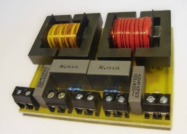
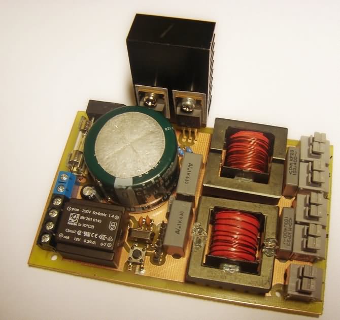
ELECTRONIC FLUORESCENT BALAST CIRCUIT SCHEMATIC
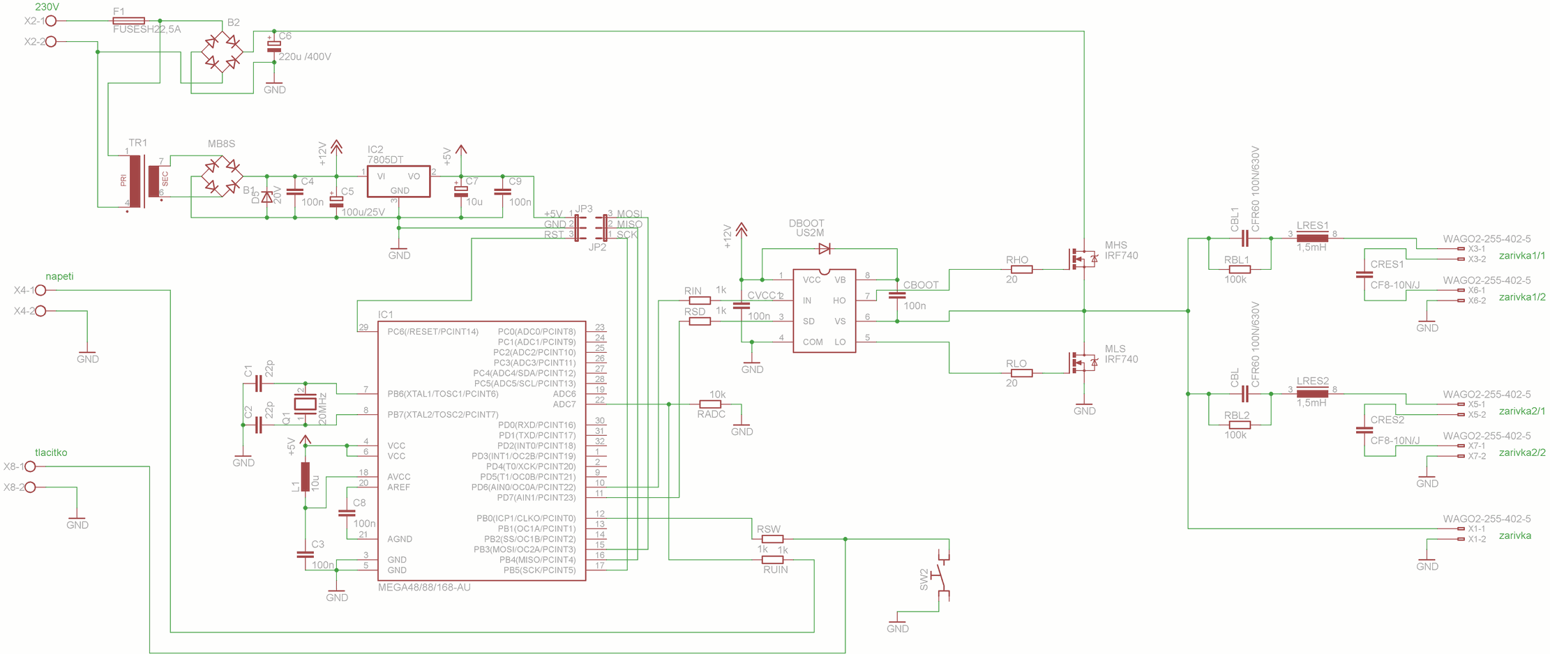
Button can change the intensity of the brightness smoothly from the maximum after the minimum and back. In short pressing leads to switching on/switching off fluorescent lamps. When the measurement has been adjusted value of the inductor, 1.6 mH and ignition/operating frequency was set to 48 kHz. At this value the voltage at the fluorescent lamp was 104 In. The maximum frequency when the fluorescent lamp still shone was 62 kHz. The wiring is designed with a microcontroller ATmega48 and an integrated circuit of the IR2104
For sorting of fluorescent lamps has been chosen parallel arrangement mainly due to the power options directly from the mains 230 V/50Hz without the need to use increasing source of tension. Another advantage of this involvement is also the choice of the number of tubes from 1 pc to 6 pcs. The control program is written so that you can simply change the frequency stored in the variable zhav, light, max, and min. All the necessary calculations for the oscillator and the AD converter are contained in the program code and for the calculation of the required frequencies, the capacitor and inductors can be use conveniently program Ballast Designer V4 from the company International Rectifier.
Source: 240W ELECTRONIC BALLAST CIRCUIT IR2104 ATMEGA48 CONTROLLED
IR2104 Ballast Circuit pcb schematic ATmega48 source code all files alternative links: 240w-electronic-ballast-circuit-ir2104-atmega48-controlled.rar alternative link2
-
How does the system determine when to start the lamps?
The system starts the lamps only when the measured input voltage is higher than 0.5 V. - What happens if the input voltage is less than 0.5 V? If the input voltage is less than 0.5 V, the system requires a test push of the button to proceed.
- At what voltage setting is the maximum brightness achieved? Maximum intensity is set when the control voltage reaches 5 V.
- Why was hysteresis introduced into the control voltage? Hysteresis was necessary due to the constant changing frequency during operation.
- What is the step value for the set hysteresis? The hysteresis has been set to a step of ±50 Hz.
- What resolution is used for transferring voltage to frequency? The resolution of the transfer of voltage to frequency is set within a range of 80 steps.
- How can the user manually change the brightness? A short press on the button switches the lamps on or off, while long pressing changes the intensity smoothly.
- What frequency range allows the fluorescent lamp to shine? The ignition and operating frequency was set to 48 kHz, with the maximum frequency being 62 kHz.