Summary of 24V 48W DIGITAL SOLDERING STATIONS ATMEGA8
Summary: A compact third-generation micro soldering station was built using 24VAC heating, full temperature control (80–450 °C), fast set jumps, stand-by at 120 °C, audible alerts, thermocouple fault detection, EEPROM-stored settings, and calibration. The design fits a small aluminum/galvanized case, uses an ATmega8-based controller with MAX6675 for temperature sensing, opto-triac switching for 24VAC heater, and a 5V regulator for electronics. PCB dimensions 88×52 mm; consumption ~0.25A during soldering; construction cost ~1400 Kč.
Parts used in the Microfibers micro-soldering station:
- R1, R2 - 33 SMD size 0805
- R3-R5 - 1k resistors
- R6, R7, R9, R12 - 1k SMD size 1206
- R8 - 2k7 SMD size 1206
- R10 - 10 SMD size 1200 (or similar 5-15 ohm)
- R11 - 4k7 SMD size 1206
- R13 - 10k SMD size 1206
- R16 - 180 SMD size 1206
- R17 - 360 SMD size 1206
- P1 - 10k Trim PT6H (standing)
- C1 - 2200 µF / 35V (RM7.5)
- C2 - 1000 µF / 16V (RM5)
- C3-C8 - 100n SMD size 1206
- C9, C10 - 100n SMD size 0805
- C11, C12 - 22p SMD size 1206
- D1 - Dual LED 5mm red + green, common cathode
- M2 - B250C1500F or KBL04 bridge rectifier
- LCD1 - PRC1602A or RC1602D 2x16 LCD with backlight
- IC1 - ATmega8-16AU microcontroller
- IO1 - 7805 voltage regulator with heatsink HS-135A-38
- IO2 - MOC3041 optocoupler (zero crossing)
- IO6 - MAX6675 thermocouple interface (SMD)
- Q1 - 12 MHz crystal
- REP1 - KPE242
- SW1 - STEC12E08 rotary encoder with push button and knob
- T1-T3 - BC817 transistors SMD SOT-23
- T4 - BT137 or BT800 triac with heatsink HS-135A-38
- ISP1 - MLW06G
- JUM1 - S1G2 jumper (or wire / zero ohm SMD resistor)
- K1, K3 - ARK500 / 2 connectors
- K2 - PSH04-03P connector
- K4 - PSH02-03P connector
- K6 - PSH02-04P connector
- PENSOL-SL20-T transformer (compatible with PENSOL SL10/20 series)
- PENSOL-IRON-N Solomon soldering iron handpiece with DIN-5 connector
- Wire jumpers - small pieces of wire (3×)
After a year of using my assembled Microfibers according to the Jendy documents23 , I decided to build 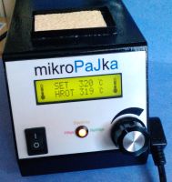 another (third) microfuel.
I wanted to reduce the dimensions, use the 24V AC heating power, to adjust the temperature better and to add additional functions …
Features of micro-drives :
- temperature range 80 ° C to 450 ° C
- continuous regulation of heating and temperature reading 3x per second
- stand-by mode with a holding temperature of 120 ° C and off LCD backlighting
- possibility of fast temperature setting – jumping after 50 ° C
- acoustic signaling of reaching the temperature during first warm-up, operating states, tip disconnection
- piezo can be switched off
- watch the delayed hand in the stand (can be switched off), after 10, 12, and 14 min sound alert, turn off the heater and backlight (auto-off) after 15 minutes. You can only wake up by pressing the button
- temperature overtemperature monitoring – or fault-disconnection of the thermocouple
- temperature probe calibration (multiplying measured temperature 0.9 to 1.1)
- all settings (and temperatures) are stored in Eeprom and are active even after the solder is switched on again
Features :
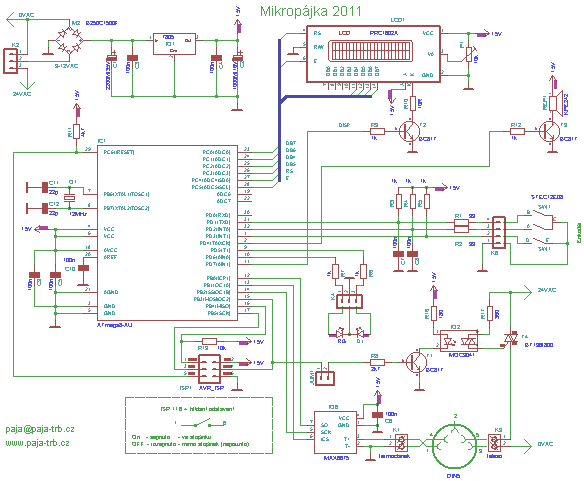
The 12V AC from the transformer is straightened and stabilized at 5V for CPU and electronics.
24V AC is switched via opto-triax IO2 (with zero switching) and triac T4 for heating the body of the handpiece.
The temperature reading from the thermocouple is in charge of the IO6 MAX6675, from which the processor reads the actual temperature, adjusts it and adjusts the heating of the body according to the settings, displays the temperature on the display, the two-color LEDs, monitors the inputs from the rotary encoder and activates the piezo …
The diagram shows a delayed-release watch switch in a stand that is connected to the ISP connector (instead of the programmer) between pins 1 and 6 (the flat cable’s terminals). If the hand is in the stand – the switch is closed. The switch does not need to be used, the microswitch will work without it.
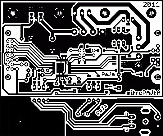
Construction :
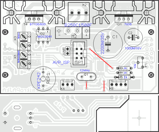
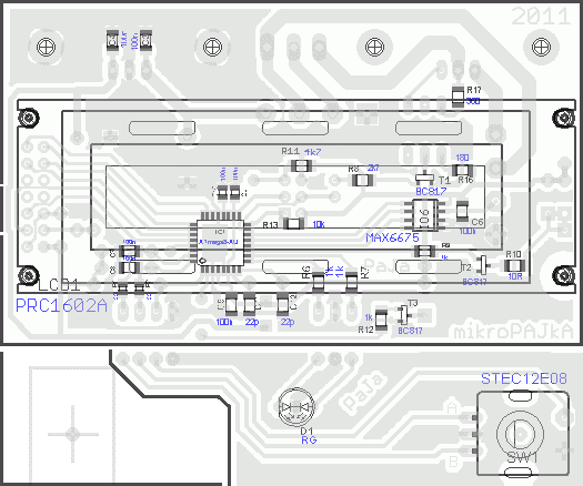
Since the design I tried to place everything on one PCB with minimal connections and wires … so the display is connected from the side of the connections through the precise breaking connectors – saving the number of wires to connect to the electronics board.
The transformer is the original Solomon soldering iron spare part, but just plug the plug from the second transformer into the PCB.
Only the main board and the feed to the rot can be used during construction. encoder and LED to solve PSH02 connectors or make a wider version with wired connection of both boards and LED and rot. encoder from the side of the links (seeing the correct height).
Short jump – Jumper does not need to be fitted – it replaces wire jumper or SMD zero resistor. I only used to test and disable body heating when programming (but there is no problem programming the processor with the jumper).
When making the box, I was inspired by the previous version. I have just achieved half the dimensions of 165mm x 100mm and 95mm height.
The front, bottom and rear parts are made of one piece of 2mm aluminum sheet. On the bottom part, for the fixing and securing of the side walls, 2 pieces of duralumin vingles 15x15mm. At the front (under the electronics) there are a couple of holes for ventilation.
The hips and the top are made of galvanized sheet metal, above the sponge bowl.
I also added a few holes for the better cooling on the side of the top, especially the 7805 cooler heats up and overheats the inside of the box.
I purchased the ZD-10A soldering iron stand , slightly adjusted the hold to raise the handle when the handle was inserted and open the microswitch (see photo ). This adjustment is unnecessary – the solder will work without a hand-held delay – not a functional auto-off.
The 230V AC supply is designed via a PC socket with a built-in tube fuse holder (sufficient 1A), the phase is switched via the switch on the front side to the primary port.
I printed the label on the front of the self-adhesive paper, cut the display window and sealed it with a transparent self-adhesive foil (the display window with a piece of foil on the other side – and the dust would not stick to the adhesive). The weight of the microfibers is less than 2kg.
Consumption :
Primary transformer (measured with a 20-meter multimeter) : melts = 0.25A / cold = 0.06A / stand-by = 0.05A
Consumption of money for construction … about 1400kč for electrical material. I do not count the iron for the construction of the box and the countless hours of production.
Program :
At the same time holding the button down and turning on the solder, you can get to calibrate the actual measured temperature at the end of the tip (the thermocouple with the meter over a drop of molten tin at the tip of the tip) . Because the read and “real” can vary slightly, it is possible to multiply the loaded temperature by 0.9 to 1.1
For this purpose, the graph is converted from Excel: Calibration Deviation Calculation . After entering the measured values compared to the display (before calibration it is good to set the calibration to 1.0 !!!), then excel calculates the multiple of the measured value – the calibration deviation.
The first step after switching on is to check the temperature, if it is less than 80 ° C, automatically switches on the heater, beeps and displays on the display of Pajea station / PaJa after 1s microPaJka / 2011 v1.5 .
From this moment, the program runs in an infinite loop and interrupts it 3 times / second Timer1, which checks for the delay of the hand and the state of the microtarget – mode of operation / stand-by
Operation – reads the temperature, calculates the deviation of the set and loaded temperature. First warm up on setting. the temperature is blinking, otherwise the LED flashes according to the regression and maintains the temperature by heating the body. The display shows the set and actual tip temperature, and if the tip temperature is exceeded (> 700 ° C = disconnect / fault), the alarm sounds and displays the Disconnected warning. Small thermometers on the sides of the display vary depending on the set and reached tip temperature (regression deviation)
Stand-by – backlight goes off, displays stand-by / 120 ° C , reads and maintains the tip temperature at 120 ° C
The MAX6675 temperature readout runs in series, then the 16-bit value moves to the right by 5 positions to obtain temperature information in ° C. The temperature is further adjusted to the calibration value and converted to the appropriate type of variable.
Encoder – in the case of rotating rot. the encoder activates an external interrupt and the program serves it. Check the condition of the second pin rot. encoder. By adding or subtracting the set temperature, the resulting value will be stored in the memory (preserved after the solder has been switched off) and displayed on the display.
Button – Second external interruption when the rot button is pressed. encoder. It stops Timer1 (3x / s will not interrupt). It then monitors the length of the keystroke and either switches the Operation / Stand-by mode or, when pressed for a longer time, jumps to the Menu, then reactivates Timer1
Menu – stops Timer1 and disables both external interruptions. The first menu item is to quickly set the temperature to 50 ° C (range 80-450 ° C) by pressing. the value is stored. Another is to allow / disable pieza and the last is to watch the delay of the hand. Finally, it will re-enable Timer1 and both external interruptions.
List of used components:
R3-R5 – 1k
R6,7,9,12 – 1k SMD size 1206
R8 – 2k7 SMD size 1206
R10-10 SMD size 1200 (or similar 5-15 ohm)
R11 – 4k7 SMD vel.1206
R13 – 10k SMD vel.1206
R16 – 180 SMD size 1206
R17 – 360 SMD size 1206
P1 – 10k Trim PT6H (Standing) C1 – 2200M / 35V (RM7,5)
C2 – 1000M / 16V (RM5)
C3-C8 – 100n SMD size 1206
C9, C10 – 100n SMD vel.0805
C11, C12 – 22p SMD size 1206
D1 – LED 5mm – red + green, spol. cathode
M2 – B250C1500F or KBL04 (TME)
LCD1 – PRC1602A LCD display 2×16 with backlight or RC1602D (TME)
IC1 – ATmega8-16AU
IO1 – 7805 + Heatsink HS-135A-38 (TME) – Best even bigger
IO2 – MOC3041
IO6 – MAX6675 SMD (from: MAX6675 TME)
Q1 – 12MHz
REP1 – KPE242
SW1 – STEC12E08 (rotary encoder with SOS button) + hat
T1-T3 – BC817 SMD SOT-23
T4 – BT137 / 800 + Heatsink HS-135A-38 (TME)
ISP1 – MLW06G
JUM1 – S1G2 + JUMP (can be connected by wire or zero SMD resistor)
K1, K3 – ARK500 / 2
K2 – PSH04-03P
K4 – PSH02-03P
K6 – PSH02-04P
PENSOL-SL20-T (TME) – Transformer to PENSOL SL10 and 20, SL10ESD, 20ES
PENSOL-IRON-N (TME) – Solomon soldering iron handpiece + DIN-5 connector
wire jumper (bridge) – a piece of wire – 3x
Source: http://paja-trb.unas.cz/elektronika/konstrukce/mikropajka_2011.html alternative
link: 24v-48w-digital-soldering-stations-atmega8.RAR
- What temperature range does the micro-soldering station support?
The station supports 80 °C to 450 °C. - Can the device use 24V AC for heating?
Yes, 24V AC is switched via an opto-triac IO2 and triac T4 for heating the handpiece body. - How often is temperature read and regulation performed?
Temperature is read and regulation runs three times per second. - Does the device support a stand-by mode?
Yes, stand-by holds 120 °C and turns off the LCD backlighting. - Is temperature calibration available?
Yes, the thermocouple measurement can be calibrated by multiplying measured temperature from 0.9 to 1.1. - Are settings preserved after power off?
Yes, all settings and temperatures are stored in EEPROM and retained after power cycling. - What temperature sensor interface is used?
The MAX6675 is used to read the thermocouple temperature. - Does the station provide overtemperature or thermocouple fault detection?
Yes, it monitors overtemperature and thermocouple disconnection and signals a fault. - How is the front panel display connected to minimize wiring?
The display is connected from the side via precision breaking connectors to reduce number of wires. - What microcontroller runs the program?
The ATmega8-16AU microcontroller runs the firmware and control loops.