
Summary of Electronic Live Capture Mousetrap
This project describes an electronic live-capture mousetrap designed to safely catch rodents using a PIC12F683 microcontroller. The system utilizes infrared sensors to detect when a rodent enters a baited box, triggering a relay-controlled door to lock it in place without harming the animal. A reset button allows for manual intervention.
Parts used in the Electronic Live Capture Mousetrap:
- PIC12F683 microcontroller
- Infrared transmitter LED
- TSOP1138 infrared receiver
- BS170 MOSFET
- Relay switch
- Push button
- Bait box enclosure
Summary
A mousetrap is a type of animal trap specialize to catch small animals, particularly rodents like rats, mice, hamsters, etc. This project is a kind of mousetrap that is intended to keep a captured animal alive. In this way, the hunter can release the captured animal later to the wild.

The PIC12F683 microcontroller acts as the heart of the project; it is programmed to meet function of the design. The sensor used in this project is a pair of infrared transmitter and receiver. An infrared LED connected to the GP2 pin of the PIC12F683 transmits continuous infrared signal to the TSOP1138 infrared receiver connected to the GP1 pin of the PIC12F683. To avoid the effect of ambient light, the generated signal at GP2 pin to the infrared LED is modulated at 38kHz frequency. Once the infrared beam is broken, the GP1 input changes, thus, the PIC12F683 reacts by triggering the GP4 pin connected to the BS170 MOSFET that act as a switch of the relay. The relay switch is set to shut the door when triggered. A push button connected at GP3 pin of the PIC12F683 is used for reset.
This project has a simple concept; the trap is built on a box fitted for a rodent to enter. The bait is placed inside the box to lure the rodent in. A sensor will be triggered once the rodent is inside the box, then a single door will shut lock behind the captured rodent.
For more detail: Electronic Live Capture Mousetrap
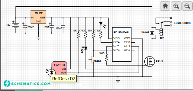
The PIC12F683 microcontroller acts as the heart of the project; it is programmed to meet function of the design. The sensor used in this project is a pair of infrared transmitter and receiver. An infrared LED connected to the GP2 pin of the PIC12F683 transmits continuous infrared signal to the TSOP1138 infrared receiver connected to the GP1 pin of the PIC12F683. To avoid the effect of ambient light, the generated signal at GP2 pin to the infrared LED is modulated at 38kHz frequency. Once the infrared beam is broken, the GP1 input changes, thus, the PIC12F683 reacts by triggering the GP4 pin connected to the BS170 MOSFET that act as a switch of the relay. The relay switch is set to shut the door when triggered. A push button connected at GP3 pin of the PIC12F683 is used for reset.
This project has a simple concept; the trap is built on a box fitted for a rodent to enter. The bait is placed inside the box to lure the rodent in. A sensor will be triggered once the rodent is inside the box, then a single door will shut lock behind the captured rodent.
For more detail: Electronic Live Capture Mousetrap
-
What is the primary function of this mousetrap?
The trap is intended to keep a captured animal alive so it can be released later. -
How does the sensor avoid interference from ambient light?
The signal sent to the infrared LED is modulated at a 38kHz frequency. -
Which component acts as the switch for the relay?
The BS170 MOSFET connected to the GP4 pin acts as the switch. -
What happens when the infrared beam is broken?
The GP1 input changes, causing the microcontroller to trigger the door shut mechanism. -
How is the trap reset after a capture?
A push button connected at the GP3 pin is used for resetting the system. -
What type of animals is this device designed to catch?
The device specializes in catching small animals like rats, mice, and hamsters.
