Summary of 8 Channel Relay Board with onboard 5V regulator
This 8-channel relay board accepts 8 inputs to drive 8 relays, serving as a general-purpose component or add-on for development boards. It features robust NPN transistor drivers, individual status LEDs, and protection diodes against back EMF, surges, and reverse polarity. The board includes an onboard 7805 voltage regulator to supply +5V DC to interface circuits, connects via 3-pin PBT connectors for loads, and uses a 10-pin Relimate connector for driving interfaces. It operates on a 12–15 V DC supply.
Parts used in the 8 Channel Relay Board:
- NPN transistors
- Relay On Indicator LEDs
- Back EMF / Surge protection diodes
- 3 Pin PBT connectors
- Reverse Polarity protection diode (D17)
- 2 pin PBT connectors
- Voltage Regulator U1 (7805)
- 10 pin Relimate Connector
This is a general purpose relay board accepting 8 inputs to drive 8 relays providing control requirement in your project. This board can also be used as an add-on card for the various Development board that we provide.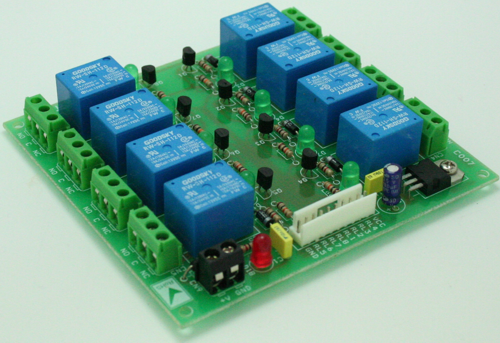
Features
- Robust Design using NPN transistor to drive each relay
- Relay On Indicator LED for each of the eight relays.
- Back EMF / Surge protection diode across each relay to protect driving circuit.
- 3 Pin PBT connector for connecting load to the relay.
- Reverse Polarity protection diode (D17) provided.
- 2 pin PBT provides easy connection of power source to the PCB.
- On Board Voltage Regulator U1 (7805) provides +5V DC supply to ongoing interface circuit connected to this board.
- A 10 pin Relimate Connector provides easy connect of this PCB to the driving interface.
- Supply voltage 12 ~ 15 V DC
Schematic
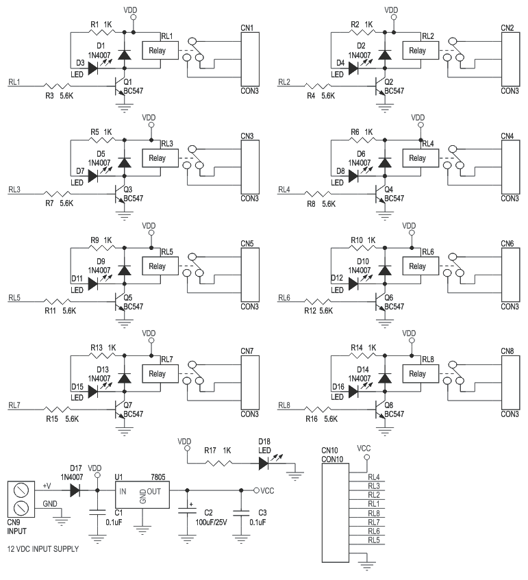
For more detail: 8 Channel Relay Board with onboard 5V regulator
- How many inputs does this relay board accept?
This is a general purpose relay board accepting 8 inputs to drive 8 relays. - Can this board be used as an add-on card?
Yes, this board can also be used as an add-on card for various Development boards. - What type of protection is provided across each relay?
A Back EMF / Surge protection diode is provided across each relay to protect the driving circuit. - Does the board have an onboard voltage regulator?
Yes, an On Board Voltage Regulator U1 (7805) provides +5V DC supply to the ongoing interface circuit. - What is the required supply voltage for operation?
The supply voltage requirement is 12 ~ 15 V DC. - How do you connect the load to the relay?
You use a 3 Pin PBT connector for connecting the load to the relay. - Is there protection against reverse polarity?
Yes, a Reverse Polarity protection diode (D17) is provided. - How is the PCB connected to the driving interface?
A 10 pin Relimate Connector provides easy connection of this PCB to the driving interface.