
Summary of From PWM to voltage
This article explains that the Arduino `analogWrite()` function uses Pulse-Width Modulation (PWM) to simulate analog voltages on microcontrollers lacking true analog outputs. By varying the pulse width and passing the signal through a resistor-capacitor low-pass filter, an average voltage between 0 and VCC is generated.
Parts used in PWM to Voltage Conversion:
- Microcontroller
- Resistor
- Capacitor
- Oscilloscope
The Arduino library has always had an “analogWrite()” function, even though the ATmega doesn’t have any way to generate a varying voltage. So why the name?
Well, what most microcontrollers can do is generate a pulse-width modulated signal, also known as PWM. That’s just a fancy way of saying that the microcontroller periodically generates a pulse, of which the width can be varied under software control.
Here’s a diagram from the Arduino PWM tutorial page:
It’s very easy to generate an approximate voltage between 0 and VCC by simply adding a resistor and capacitor to act as low-pass filter:
That image came from an excellent article by Scott Daniels about this same topic on the ProvideYourOwn.com website. Check it out for much more background information.
So how do these two little components turn PWM into a voltage?
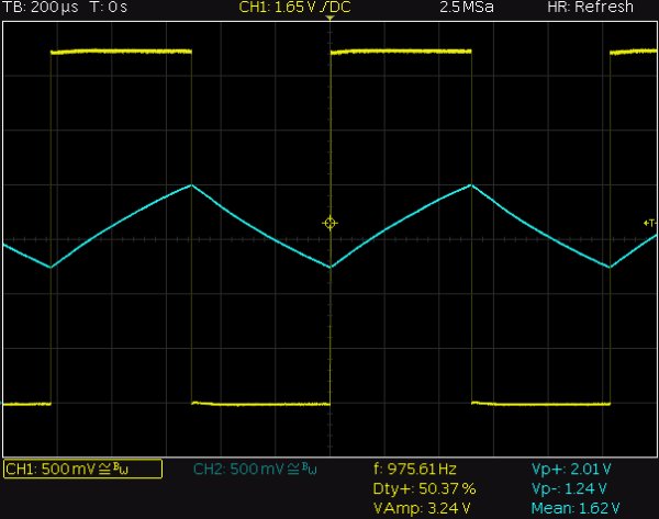
To see what’s going on, we can tie the resistor to a PWM pin, call “analogWrite(N,128)” to set a 50% duty cycle, i.e. halfway, and then watch the result on the oscilloscope:
For more detail: From PWM to voltage
- How does analogWrite() generate a varying voltage?
The microcontroller generates a pulse-width modulated signal where the pulse width is varied under software control. - What components turn PWM into a voltage?
A resistor and capacitor are added to act as a low-pass filter. - Can you generate an approximate voltage between 0 and VCC?
Yes, it is very easy to generate this range by using the resistor and capacitor filter. - What happens when you set a 50% duty cycle?
Tying the resistor to a PWM pin with a 50% duty cycle results in a specific waveform observable on an oscilloscope. - Does the ATmega have a way to generate a varying voltage directly?
No, the ATmega does not have any way to generate a varying voltage directly. - What is the purpose of the low-pass filter?
The low-pass filter converts the periodic pulses into an approximate steady voltage. - Who wrote the article about this topic on ProvideYourOwn.com?
Scott Daniels wrote the excellent article about this topic on the ProvideYourOwn.com website.
