Summary of Breaking out a QFP Attiny88 AVR
The author describes prototyping with the Attiny88 microcontroller, highlighting its cost-effectiveness and SPI capabilities. Since QFP-32 packages are difficult to solder by hand, the project involves using a QFP32-to-DIP32 breakout board. The process includes tinning pads, applying flux, tacking corners for alignment, and soldering remaining pins carefully to avoid bridging. The guide also covers sourcing cheap passive SMD components like capacitors and resistors, emphasizing the challenge of handling small 0603 and 0805 parts.
Parts used in the Breakout a QFP Attiny88 AVR:
- Attiny88 QFP-32 microcontroller
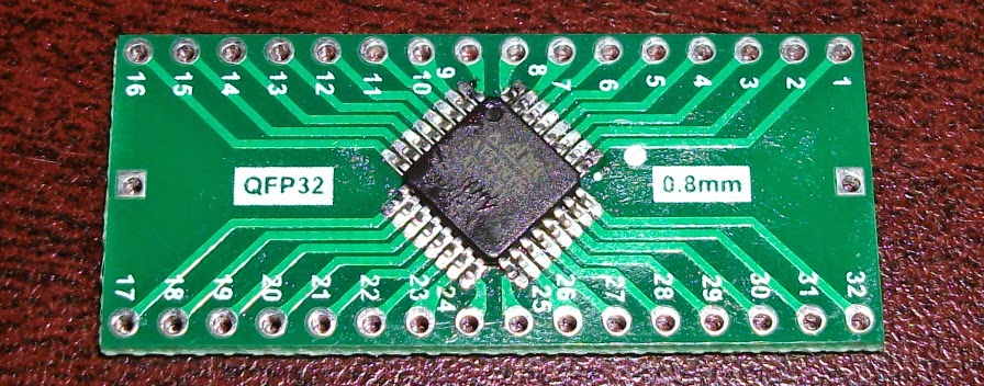
- QFP32 to DIP32 breakout board
- Pencil-style soldering iron
- Solder wick
- Flux
- 0.1uF ceramic capacitors (0805)
- 0805 resistors
- 0603 resistors
- Multimeter
Several months ago I noticed the Attiny88. It has several more I/O than the Atmega328, with an extra Port A and PC7. And unlike most of the other Attiny series, it has real SPI instead of USI, so libraries using SPI don’t have to be re-written. At just 86c for qty 1, it is the also the cheapest AVR with 8KB flash. Since QFP-32 parts aren’t easy to work with, I searched for breakout boards and found QFP32 to DIP32 boards that would allow me to use them in a small breadboard.
I had lots of experience soldering through-hole parts, but not surface-mount. With the pin spacing of only 0.8mm, soldering individual pins with a standard soldering iron initially seemed like an impossibility. After reading some guides and watching a couple youtube videos, I realized I should be able to solder the QFP-32 chips with my trusty old pencil-style soldering iron.
Besides the QFP Atiny, I figured I’d get some passive SMD parts as well. I was surprised how cheap they are – 50c for 100 0.1uF ceramic capacitors and $3 for 1000 0805 resistors. I got a little carried away and even ordered a full reel of 5000 15K 0603 resistors that were on special for $5. Besides being more than I’ll probably ever use, the 0603 size is almost too small for hand soldering. Even the 0805 parts, at .08″ or 2mm long are a bit tricky to handle. The 0603 parts, at 1.6 by 08.mm, are the size of a bread crumb.
After all the parts arrived, I started by tinning the pads on the breakout board. That turned out to be a mistake since the leads from the tiny88 would slide off the solder bumps when I tried to solder the first lead. A dab of flux on the bottom of the chip helped keep it in place, but for the second chip I did I only tinned the pads in to opposite corners. I tack soldered one lead in one corner, adjusted it until it was straight, and then soldered the other corner.
Once the chip is held in place with two leads (double and triple-check it while it is easy to adjust), the rest of the leads can be soldered. On the first chip I tried I used too much solder, which caused bridging between some of the leads. So have some solder wick on hand. When I soldered the second board, I only tinned the tip of my iron, which was enough solder for about 4 leads, and avoided bridging. After the soldering is done check continuity between the leads and the DIP holes with a multimeter. Also check for shorts by testing the adjacent dip holes.
For more detail: Breaking out a QFP Attiny88 AVR
- Why did the author choose the Attiny88?
It offers more I/O than the Atmega328, includes real SPI, and is the cheapest AVR with 8KB flash at 86 cents. - What tool was used to solder the QFP-32 chips?
The author used a standard pencil-style soldering iron after watching guides and videos. - How much do 0805 resistors cost per unit?
They cost $3 for 1000 units, making them very affordable. - What mistake was made when tinning the breakout board pads initially?
Tinning all pads caused the chip leads to slide off the solder bumps during the first attempt. - How should the chip be secured before soldering all leads?
Apply flux to the bottom, tack solder one lead in a corner, adjust for straightness, then solder the opposite corner. - What caused bridging between leads on the first chip?
Using too much solder resulted in bridging between some of the leads. - How can you verify the soldering quality after completion?
Check continuity between leads and DIP holes and test adjacent DIP holes for shorts using a multimeter. - What size resistor reel was ordered as a special deal?
A full reel of 5000 15K 0603 resistors was ordered for $5.