Summary of Light Sensor LED Brightness Control System with ATMEGA328 UNO V3.0 R3 for Arduino
This article outlines building a light sensor LED brightness control system using an ICStation UNO R3. It details connecting a 5V DC power supply, breadboard, jumper wires, and pins to interface an analog light sensor with a highlight LED. The setup allows the LED's brightness to adjust based on ambient light detected by the sensor.
Parts used in the Light Sensor LED Brightness Control System:
- ICStation UNO R3 with USB compatible with Arduino
- Bread board
- Highlight LED light emitting diode
- Analog light sensor
- Hard jumper wire
- 4 PCS jumper wire
- 5 Voltage DC power supply
- 3 PCS of pins
- 3P DuPont line
Step 1: Components list
1.ICStation UNO R3 with USB compatible with Arduino
2.Bread board
3.Highlight LED light emitting diode 4.Analog light sensor
5.Hard jumper wire
6.4 PCS jumper wire
7. 5 Voltage DC power supply
8.3 PCS of pins
9.3P DuPont line
2.Bread board
3.Highlight LED light emitting diode 4.Analog light sensor
5.Hard jumper wire
6.4 PCS jumper wire
7. 5 Voltage DC power supply
8.3 PCS of pins
9.3P DuPont line
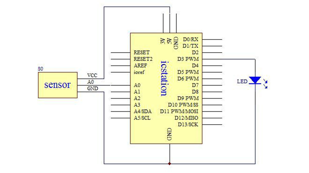
Step 2: Schematic Diagram
Step 3: Connect the +5V Power Supply and GND of development board to the bread board
The red wire connects the power supply and the black wire connects the GND
Step 4: Connect the analog light sensor with 3P DuPont line
Connect the analog light sensor with 3P DuPont line and connect the pin to the another end of 3P DuPont line.
- What components are required for this project?
The project requires an ICStation UNO R3, bread board, highlight LED, analog light sensor, hard jumper wire, 4 PCS jumper wire, 5 Voltage DC power supply, 3 PCS of pins, and 3P DuPont line. - How do you connect the power supply to the development board?
The red wire connects the +5V Power Supply and the black wire connects the GND to the bread board. - Can the analog light sensor be connected directly without wires?
No, the analog light sensor must be connected using a 3P DuPont line. - Which pin configuration is used for the light sensor connection?
The analog light sensor is connected via a 3P DuPont line to the pins at the other end. - Does the system use a 5V or 12V power source?
The system uses a 5 Voltage DC power supply. - What type of LED is specified for this circuit?
A Highlight LED light emitting diode is used in this project. - How many pins are needed for the connections?
The parts list specifies using 3 PCS of pins. - Is a bread board necessary for this assembly?
Yes, a bread board is listed as a required component for connecting the power supply and other parts.