
Summary of DIY AVR Development Board with Atmega128
This article details the design of a custom AVR development board using the Atmega128A-AU microcontroller. The author utilized the toner transfer method for PCB manufacturing to create a board featuring essential support components like voltage regulation, power input, reset functionality, and debugging LEDs. The design includes connections for two crystals: an 8MHz clock and a 32.768KHz real-time clock oscillator.
Parts used in the DIY AVR Development Board:
- Atmega128A-AU microcontroller
- AMS1117 voltage regulator
- DC Jack
- Reset button
- Power LED
- 8Mhz quartz crystal
- 32.768KHz crystal
- Pin headers
For many of my previous projects I used AVR Microcontrollers extensively. I started with the Atmega8 and moved to superior AVR variants depending on the application complexity and requirements. Before designing any particular application, I usually do my research on a development board. It is a PCB featuring the target microcontroller and minimal support logic that usually covers a regulated power supply, pin headers to connect peripherals and/or a few LEDs used for basic debugging.
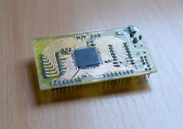
Such boards are available in many shapes and colours, from simple to complex and most of the times they are affordable (after all we’re talking about a minimal PCB with a microcontroller and a few, mostly passive, components).
For some various reasons I had to design my own core development board featuring an Atmega128A-AU microcontroller from Atmel. This is an excellent piece of silicon, featuring 128KB of flash memory, a max operating frequency of 16Mhz and a generous total count of 64 pins offering plenty of I/O options.
When doing prototype PCBs I usually go for a toner transfer manufacturing process, that might have its issues but can prove reliable once you get it right.
Development board schematics and PCB
This was rather simple to do: designing a board that connects most of microcontroller’s I/O ports to pin headers, and for the rest traces to a main 8Mhz quartz crystal, a voltage regulator (AMS1117), a DC Jack, a reset button and a LED to show when power is connected. There is a second 32.768KHz crystal that I plan to use with the Atmega128’s internal real time clock circuit.
For more detail: DIY AVR Development Board with Atmega128
- What microcontroller is featured in this custom development board?
The board features an Atmega128A-AU microcontroller from Atmel. - How much flash memory does the Atmega128A-AU have?
The microcontroller features 128KB of flash memory. - What manufacturing process was used for the prototype PCBs?
The author used the toner transfer manufacturing process. - Does the board include a real time clock circuit?
Yes, it includes a 32.768KHz crystal planned for use with the internal real time clock circuit. - What is the maximum operating frequency of the microcontroller?
The microcontroller has a max operating frequency of 16Mhz. - Which voltage regulator is used on the board?
An AMS1117 voltage regulator is used. - What components are connected to pin headers on the board?
Most of the microcontroller's I/O ports are connected to pin headers. - What is the purpose of the second crystal on the board?
The second crystal is a 32.768KHz unit intended for the real time clock circuit.
