Summary of Designing and building a 2m low pass filter
This article details the DIY construction of a 5-pole T-configuration Chebyshev low-pass filter designed for the 2-meter amateur radio band (148 MHz). The author outlines a five-step design process involving coefficient selection from the ARRL Handbook and component conversion. A key lesson shared is the importance of selecting a cutoff frequency at least 10% above the target band maximum to avoid poor insertion loss, recommending 162 MHz over 150 MHz.
Parts used in the 2m Low Pass Filter:
- Inductors (created via turns on a core)
- Capacitors
- Filter Core
- ARRL Handbook (for normalized coefficients)
I’ve been playing with the DRA818V modules that have been making quite a stir in the amateur radio world at the moment. I haven’t gotten one on a spectrum analyzer yet, but I have reason to believe that it will require a low pass filter to be RF legal. I’ll write more about that once I get a look at it, but figured I’d first built myself a low pass filter in case I need it (if not for these modules, but some other VHF project in the future).
My process for building a low pass filter went as follows:
- Select the type of filter and cutoff frequency desired
- Look up normalized coefficients in the ARRL Handbook
- Divide these coefficients by the cutoff frequency
- Convert the inductances into turns on some core and capacitors into the nearest values
- Build the filter.
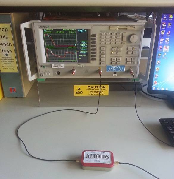
Since I wanted this filter for 2m, the highest frequency I’m interested in passing is 148MHz, so I selected a cutoff frequency of 150MHz. In hind-sight, this was a poor choice, since a -3dB point only 2MHz above the band caused for a lousy insertion loss. A better choice would have been 10% higher than the top of the band, so 148MHz * 1.10 = 162MHz
I decided to build a 5 pole T configuration Chebyshev filter with 0.1dB of ripple.
I’ve been playing with the DRA818V modules that have been making quite a stir in the amateur radio world at the moment. I haven’t gotten one on a spectrum analyzer yet, but I have reason to believe that it will require a low pass filter to be RF legal. I’ll write more about that once I get a look at it, but figured I’d first built myself a low pass filter in case I need it (if not for these modules, but some other VHF project in the future).
My process for building a low pass filter went as follows:
My process for building a low pass filter went as follows:
- Select the type of filter and cutoff frequency desired
- Look up normalized coefficients in the ARRL Handbook
- Divide these coefficients by the cutoff frequency
- Convert the inductances into turns on some core and capacitors into the nearest values
- Build the filter.
Since I wanted this filter for 2m, the highest frequency I’m interested in passing is 148MHz, so I selected a cutoff frequency of 150MHz. In hind-sight, this was a poor choice, since a -3dB point only 2MHz above the band caused for a lousy insertion loss. A better choice would have been 10% higher than the top of the band, so 148MHz * 1.10 = 162MHz
I decided to build a 5 pole T configuration Chebyshev filter with 0.1dB of ripple.
For more detail: Designing and building a 2m low pass filter
- Why was a 150MHz cutoff frequency considered a poor choice?
A -3dB point only 2MHz above the 148MHz band caused lousy insertion loss. - What is the recommended cutoff frequency calculation for the 2m band?
The author suggests setting it 10% higher than the top of the band, resulting in 162MHz. - What type of filter configuration was built?
A 5 pole T configuration Chebyshev filter with 0.1dB of ripple was constructed. - How are inductance values determined during the build process?
Normalized coefficients from the ARRL Handbook are divided by the cutoff frequency and converted into turns on a core. - What resource provides the normalized coefficients for this design?
The ARRL Handbook is used to look up the normalized coefficients. - Can this filter be used for projects other than the DRA818V modules?
Yes, the author built it for potential future VHF projects if needed. - What ripple value was selected for the Chebyshev filter?
The design utilized 0.1dB of ripple. - What is the highest frequency the author intended to pass?
The highest frequency of interest for passing was 148MHz.