
Summary of Waveform Generation using AVR Microcontroller (Atmega16) Timers
This article details generating a 5 kHz square wave using the ATmega16 microcontroller's Timer 0 in Clear Timer on Compare (CTC) mode. It explains configuring specific registers to toggle the OC0 pin automatically upon compare match, utilizing interrupts for continuous output. The project involves calculating prescaler values and OCR settings to achieve the desired frequency, with code provided to initialize the timer and handle the interrupt service routine.
Parts used in the Waveform Generation using AVR Microcontroller (Atmega16) Timers:
- ATmega16 Microcontroller
- C.R.O (Cathode Ray Oscilloscope)
At times we come across applications or situations wherein we need to generate square waves with the microcontroller. The square wave can be generated by programming a pin which toggles between 0 and 1 with a certain time delay. Alternatively, the inbuilt feature of AVR timers can be used in square wave generation. The advantage of using AVR timers in wave form generation is that the output pin toggles automatically when the timer condition are fulfilled. This article focuses on usage of AVR timer for simple square wave generation.
There are four specified pins in ATmega16 for waveform generation. Each pin can be operated by their corresponding timer only. The following table provides information about it.
Modes in Timers:
The AVR Timers work in different modes of operation. There are following modes of operation:
1. Normal mode
2. Clear timer on Compare (CTC) match mode
Delay generation using Normal and CTC mode has been described in previous articles. These two modes are also used in square wave form generation. Phase correct PWM and Fast PWM modes are used for PWM generation.
Wave form generation:
It is better to use CTC mode instead of Normal mode because in CTC mode, frequency can be easily adjusted. ?
When the Timer is triggered, register TCNTn counts the value constantly as timer started. Each timer has an OCRn (Output Compare Register), which is continuously compared with TCNTn register. In CTC mode whenever match occurs, OCFn (Output Compare Flag) will set to 1. If continuous wave form generation is required, OCFn must be reset again. Alternatively, if OCIEn (Output Compare interrupt) and Global interrupt flags in SREG are set, OCFn will reset automatically after interrupt execution.
In the earlier article, Timer register TCCR0 is explained. The bits WGM0 [1:0] are programmed to select waveform generation mode. The following table shows the combination of bits to select modes of operation:

The Register TCCR0 also consists COM0 [1:0] bits. These bits are used to select functionality of OC0 pin. Following table shows function of COM 0[1:0]:

Objective- To generate square wave form of 5 KHz frequency by using timer 0.
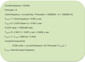
Calculation for frequency
Programming steps:
1. Select CTC mode by programming WGM0 [1:0] bit.
2. Program COM0 [1:0] bits and select “toggle OC0 if compare match”.
3. Set OC0 (PB3) pin as output pin.
4. Set OCIE0 bit of TIMSK register.
5. Enable global interrupt by “sei ()” command.
Circuit description:
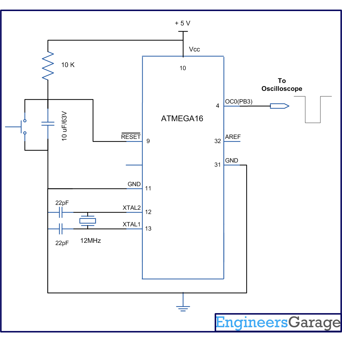
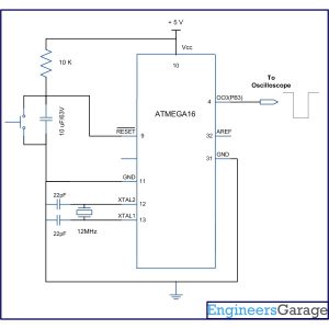
The connection of ATmega16 for this experiment is shown in circuit diagram. Since timer0 is used, hence the OC0 pin is connected to C.R.O to observe wave form.
Output wave form:
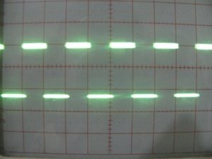
The following picture shows the output wave form which is received on CRO. The measured frequency of wave is 5 KHz.
Project Source Code
###
// Program to Generate waveform using AVR Microcontroller (Atmega16) Timers
#include<avr/io.h>
#include<util/delay.h>
#include<avr/interrupt.h>
void t0_init(void);
#define FREQ 12000000 // crsytal freqeuncy
#define PRECSALER 8
#define F_OUT 5000 // output frequency
#define OCR0_VALUE ((((FREQ/2)/PRECSALER)/F_OUT)-1)
int main()
{
t0_init(); // timer initialize
sei(); // enable global interrupts
while(1);
}
void t0_init()
{
// WGM0[1:0]= 10, for CTC mode
// COM0[1:0]= 01, to toggle OC0 on compare match
// CS0[2:0] =010. for prescaler 8
TCCR0=(1<<WGM01)|(1<<COM00)|(1<<CS01);
DDRB|=(1<<PB3); // select as output pin
TIMSK|=(1<<OCIE0);//enable output compare interrupt
}
ISR(TIMER0_COMP_vect) // interrupt subroutine
{
OCR0=(uint8_t)OCR0_VALUE; //put OCR value
}
###
Circuit Diagrams
| Circuit-Diagram-of-Waveform-Generation-using-AVR-Microcontroller-Atmega16-Timers |
For more detail: Waveform Generation using AVR Microcontroller (Atmega16) Timers
- How can a square wave be generated using an AVR microcontroller?
A square wave can be generated by programming a pin to toggle between 0 and 1 or by using the inbuilt feature of AVR timers where the output pin toggles automatically when timer conditions are fulfilled. - Which mode is better for adjusting frequency in waveform generation?
It is better to use CTC mode instead of Normal mode because in CTC mode, frequency can be easily adjusted. - What happens when a match occurs in CTC mode?
In CTC mode whenever a match occurs, OCFn will set to 1, and if global interrupt flags are set, OCFn will reset automatically after interrupt execution. - How do you select the waveform generation mode in Timer 0?
The bits WGM0 [1:0] in the TCCR0 register are programmed to select the waveform generation mode. - What is the function of COM0 [1:0] bits in the TCCR0 register?
These bits are used to select the functionality of the OC0 pin, such as selecting to toggle OC0 if a compare match occurs. - What is the objective of the described project?
The objective is to generate a square wave form of 5 KHz frequency by using timer 0. - Which pin is connected to the C.R.O to observe the waveform?
Since timer0 is used, the OC0 pin is connected to the C.R.O to observe the waveform. - What value is assigned to the FREQ define in the source code?
The FREQ define is set to 12000000 representing the crystal frequency. - How is the global interrupt enabled in the code?
The global interrupt is enabled by using the sei command. - What does the ISR subroutine do during each timer compare interrupt?
The ISR subroutine puts the OCR0_VALUE into the OCR0 register.
