
Summary of Phase Correct PWM (Pulse Width Modulation) Mode of AVR microcontroller Timer
Summary: This article explains generating PWM using ATmega16 timers, focusing on Phase Correct PWM mode with Timer0 to produce a 75% duty-cycle output on OC0. It covers mode selection (WGM0=01), COM0 settings for inverting/non-inverting output, OCR calculation, frequency formula, circuit connections (OC0 to CRO), initialization code, and an ISR that loads OCR0. Example results show a measured frequency ~23.54 kHz using a 12 MHz crystal and no prescaler.
Parts used in the Phase Correct PWM (Pulse Width Modulation) Mode of AVR microcontroller Timer Project:
- ATmega16 microcontroller
- 12 MHz crystal (implied by FREQ constant)
- Oscilloscope / CRO (to observe waveform on OC0 pin)
- Power supply for ATmega16
- Connecting wires and breadboard or PCB
- Microcontroller programming tool (to load the code)
Pulse Width Modulation is well known technique for controlling power electronics devices like SCR, IGBT etc. PWM is also used in motor speed controlling. Square wave generation by using AVR timers is explained in previous article. The AVR timers have feature of PWM wave generation as well .This article describes PWM generation capability of AVR timers.
There are four in-built PWM channels in ATmega16. The PWM outputs are received on pins OC0, OC1A, OC1B and OC2. Readers can refer the previous article which gives explanation of these pins. There are two modes of operation of AVR timer which are able to generate PWM signal.
1. Phase correct PWM mode
PWM generation by Phase correct PWM mode:
The Phase correct PWM mode can be selected by assigning bits WGM0[1:0]=01. This mode is based on dual slope operation. In dual slope operation, TCNTn counts from bottom value to maximum value and maximum value to bottom value. The OCRn register compares the value with the TCNTn register constantly during up-counting and down-counting. On compare match PWM output pin (OCn) behaves according to inverting or non-inverting mode which can be selected by programming of COMn [1:0] bits. The following table shows bit setting of COM [1:0] bits:
Phase correction PWM mode is preferred for motor controlling because dual- slope operation provides symmetric wave generation. Duty cycle of pulse can be varied by writing the values to OCRn register. The OCRn value can be calculate by the following formula:

For example: if duty cycle is 75%
OCR value = (75÷100) × 256
Frequency of PWM output will be
Frequency of PWM output will be

Objective : Generate PWM signal of duty cycle 75% from timer 0.
Circuit description:
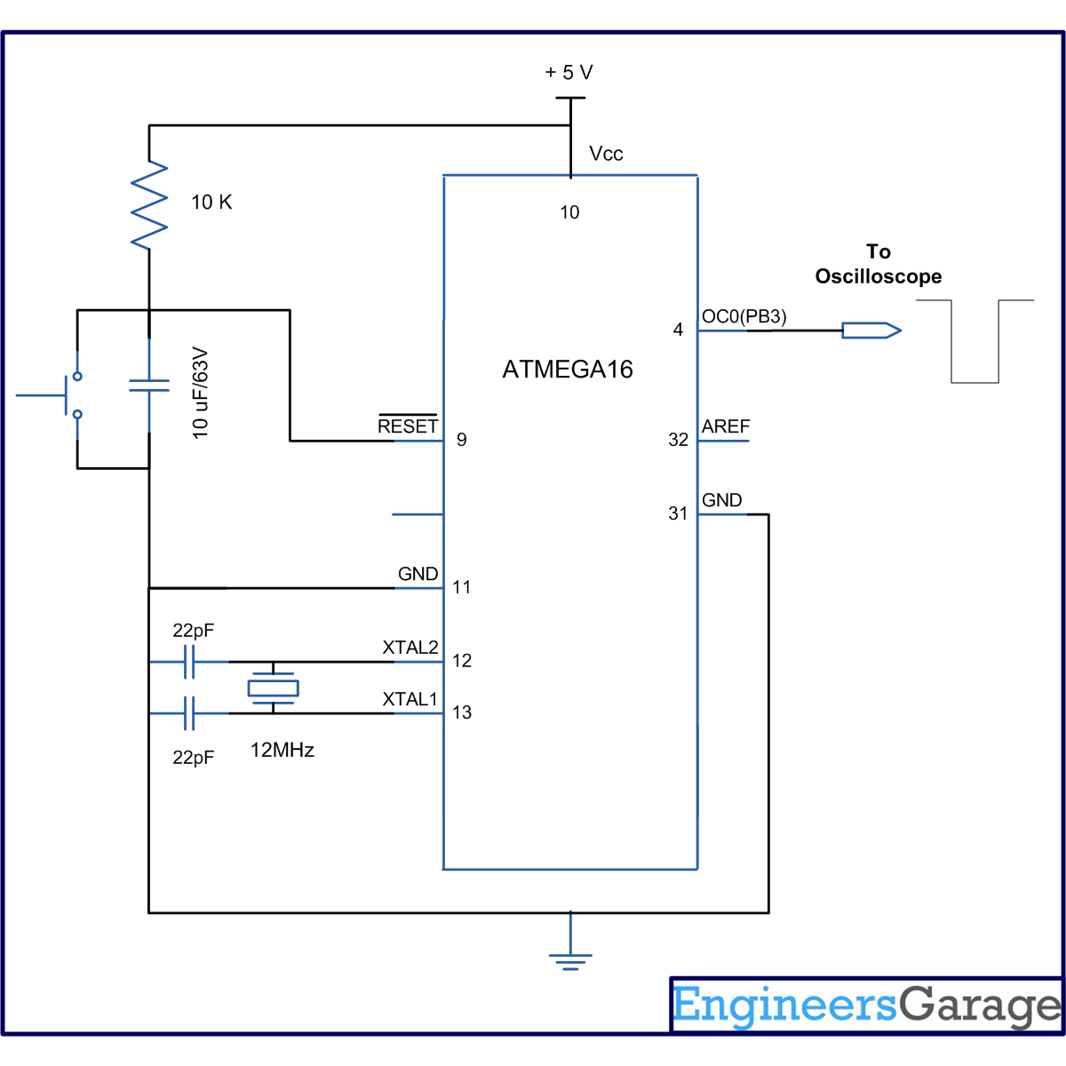
The connection of ATmega16 is shown in circuit diagram. Since, Timer0 is used to generate PWM wave then output is taken on OC0 pin, so pin no.4 is connected to C.R.O to observe the waveform.
Programming steps:
1. Select Phase Correct PWM mode by programming WGM0 [1:0] bit.
2. Program COM0 [1:0] bit and select inverting or non-inverting mode .
3. Set OC0 pin as output pin.
4. Set OCIE0 bit of TIMSK register.
5. Enable global interrupt by “sei()” command.
Output wave:
Frequency calculation by formula:
Output frequency = Crystal frequency÷(Prescaler ×510)
= 12000000÷(1×510)
= 23529.41 = 23.53KHz
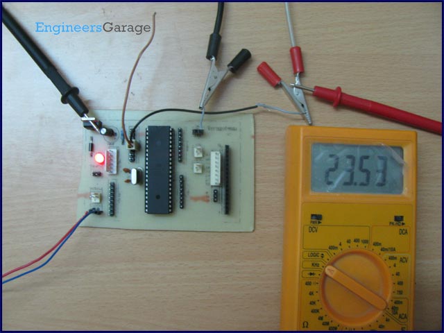
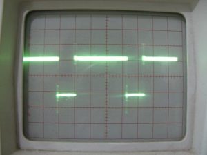
The following picture shows the output wave form which is received on CRO. The measured frequency of wave is 23.54 KHz.
Project Source Code
###
// Program to use Phase Correct PWM (Pulse Width Modulation) Mode of AVR microcontroller Timer
#include<avr/io.h>
#include<util/delay.h>
#include<avr/interrupt.h>
#define FREQ 12000000
#define duty_cycle 75 // duty cycle require
#define prescaler 1
#define OCR_value ((duty_cycle*256)/100)
void t0_pwm_init(void);
int main()
{
t0_pwm_init();
sei(); // enable global interrupt
while(1);
}
void t0_pwm_init() //// intiatialize of timer0
{
// WGM0[1:0]= 01, for Phase Correct PWM mode
// COM0[1:0]= 10, to select non inveting mode
// CS0[2:0] =001. for no prescaler
TCCR0=(1<<WGM00)|(2<<COM00)|(1<<CS00);
DDRB|=(1<<PB3); // selcetOC0 as output pin
TIMSK|=(1<<OCIE0); //enable Output compare interrupt
}
ISR(TIMER0_COMP_vect) // interrupt subroutine
{
OCR0=(uint8_t)OCR_value; // put OCR value
}
###
Circuit Diagrams
Circuit-Diagram-of-Phase-Correct-PWM-Pulse-Width-Modulation-Mode-of-AVR-microcontroller-Timer
- How is Phase Correct PWM mode selected on Timer0?
By setting WGM0 bits to 01. - How do you select non-inverting PWM output?
Set COM0 bits to 10 for non-inverting mode. - What pin provides the PWM output for Timer0?
OC0 pin (PB3) provides Timer0 PWM output. - How is the OCR value calculated for a 75% duty cycle?
Use OCR value = (duty_cycle ÷ 100) × 256; for 75% OCR = (75×256)/100. - What is the PWM frequency formula in Phase Correct mode?
Output frequency = Crystal frequency ÷ (Prescaler × 510). - What prescaler setting was used to get ~23.54 kHz with a 12 MHz crystal?
No prescaler (prescaler = 1) was used. - How is OC0 configured as an output in code?
By setting DDRB bit PB3: DDRB |= (1 << PB3). - How is the OCR0 register updated in the example?
OCR0 is assigned inside the TIMER0_COMP interrupt service routine using OCR_value. - What interrupt is enabled for updating OCR0?
The Output Compare Match interrupt for Timer0 (OCIE0) is enabled in TIMSK. - Why is Phase Correct PWM preferred for motor control?
Because dual-slope operation provides symmetric wave generation.
