
Summary of Stepper Motor Angle Control using AVR Microcontroller
This article details a project using an AVR microcontroller to position a stepper motor at specific angles ranging from 0 to 360 degrees in 15-degree increments. Users input the desired angle via buttons, and the system rotates the motor forward or backward to reach the target. The circuit utilizes an ATMega32 microcontroller, a ULN2003A driver, an LCD display, and push buttons for control.
Parts used in Stepper Motor Angle Control:
- ATMega32 AVR Microcontroller
- ULN2003A Current Driver Chip
- Unipolar Stepper Motor
- LCD Display
- Push Buttons (SW1, SW2, SW3)
- 1K Potentiometer
- 16 MHz Crystal
- Two 22pf Capacitors
- Pull-up Resistors
There are many applications in which it is required to set the position of an object at a desire angle. Some of the examples are
1. Satellite Dish Antenna positioning
The Satellite Dish Antenna should be in straight alignment with Satellite in Space to receive signal with maximum strength. So it’s required to position the Dish Antenna at a certain angle
2. Aileron, Elevator and Rudder positioning in Aircraft
In an Aircraft it is required to position Aileron, Elevator and Rudder at a desired angle to increase or decrease the lift, to change direction and to increase or decrease the speed
3. Rudder Positioning in Ship
To move ship in a specific direction it is required to set an angle of Rudder located in front of the Propeller
4. Tank Gun or Howitzer Positioning
To hit the bull’s eye (Target) the Tank Gun (or Howitzer) must be positioned to specific angle
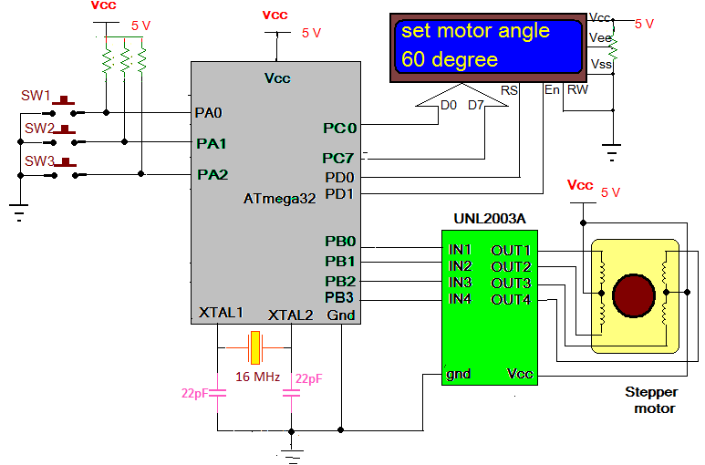
This project demonstrates how any device or object can be positioned to desired angle. The circuit presented here demonstrates how to position Stepper Motor at a specific Angle using AVR microcontroller. The desired Angle Position is entered by user and when He presses the button to rotate motor, the motor starts rotating and rotates till it reaches that angle. The angle can be entered in step of 15o between 0o to 360o. User can increment or decrement angle value in step of 15o and set the desire angle. Based on set angle motor rotates forward (CCW) or reverse (CW). Like if current motor angle is 60o and user enters 90o then motor rotates CCW and if user enters 30o motor rotates CW.
System Circuit Diagram
As shown in figure the circuit is build using AVR microcontroller ATMega32, Current Driver Chip ULN2003A, LCD and few push buttons. 3 push buttons (SW1, SW2 and SW3) are connected to PORTA pins PA0 – PA2 such that when any buttons is pressed logic 0 is given as input to that pin. Normally all 3 pins are given logic 1 by connecting them to Vcc through pull-up resistors. PORTB pins PB0 – PB3 are connected to input pins of ULN2003A. These pins drive stepper motor. The output of ULN drives four coils of unipolar stepper motor. The common terminal of motor coils and ULN chip is connected to Vcc. PORTC drives data pins of LCD and two LCD control pins RS and En are driven by PORTD pins PD0 and PD1 respectively. Control pin RW is connected to ground. A 1K pot is connected to brightness control pin Vee (3) as shown. It can be used to adjust LCD brightness. A 16 MHz crystal is connected to crystal input pins of ATMega32 along with two 22pf capacitors as shown.
System Operation
· When circuit is switched on the LCD displays set angle as 0 degree. The motor also rests at 0 degree
· By pressing SW1 the angle can be increased in step of 15 degree. Similarly to decrease angle press SW2.
· After selecting desire angle when SW3 is pressed, the stepper motor rotates till desire angle and waits for next angle value
· The angle value can be increased or decreased by pressing SW1 or SW2
· If new selected angle value is less than previous angle value then motor rotate reverse. E.g. if motor is at an angle 75o and now new set angle value is 30o then motor rotates reverse
· But if new selected angle value is higher, then motor rotates forward
Complete Circuit Operation is due to the software program embedded into AVR microcontroller. First let us see the logic behind the program.
For more detail: Stepper Motor Angle Control using AVR Microcontroller
-
What components are used to build the circuit?
The circuit is built using an ATMega32 microcontroller, ULN2003A driver chip, LCD, push buttons, a 1K pot, a 16 MHz crystal, and two 22pf capacitors. -
How can the user increment the angle value?
The angle can be increased by pressing button SW1 in steps of 15 degrees. -
How does the motor behave if the new angle is lower than the current one?
If the new selected angle is less than the previous value, the motor rotates in reverse (CW). -
What happens when the circuit is first switched on?
When the circuit is switched on, the LCD displays 0 degrees and the motor rests at 0 degrees. -
Which pins on PORTA are connected to the push buttons?
Three push buttons are connected to PORTA pins PA0, PA1, and PA2. -
How is the LCD brightness adjusted?
A 1K potentiometer connected to the Vee pin of the LCD is used to adjust the brightness. -
Can the motor rotate to any arbitrary angle?
No, the angle can only be entered in steps of 15 degrees between 0 and 360 degrees. -
What determines the direction of motor rotation?
The direction is determined by whether the desired angle is higher (CCW) or lower (CW) than the current angle.
