
Summary of Photocell or LDR
This article explains Light Dependent Resistors (LDRs), sensors that change resistance based on light intensity. They are low-cost and easy to use but inaccurate for precise measurements, with resistance dropping from 10Mohm in darkness to 1Kohm in light. The text details testing methods using a multimeter and provides a circuit example where an LDR controls an LED via an ATmega328 microcontroller.
Parts used in the Photocell Circuit Project:
- Photocell or Photo Resistor (LDR)
- Pull down resistor
- Multimeter
- LED
- ATmega328 board
- Breadboard
A photocell or photo resistor is a Light Dependent Resistors (LDR). LDR’s are sensors that detect light. They are small, inexpensive, low-power, easy to use and don’t wear out.
Overview
A photocell or photo resistor is a Light Dependent Resistors (LDR). LDR’s are sensors that detect light. They are small, inexpensive, low-power, easy to use and don’t wear out.
An LDR is a resistor that changes its resistive value (in ohms Ω) depending on how much light is shining onto it. They are very low cost, easy to get in many sizes and specifications, but are very innacurate. Each LDR sensor will act a little differently than the other, even if they are from the same batch. The variations can be really large, 50% or higher! For this reason, they shouldn’t be used to try to determine precise light levels. Instead, you can expect to only be able to determine basic light changes. When light falls on the sensor the resistance will drop. When it is dark the resistance can be as much as 10Mohm, when the light increases the resistance can drop to 1Kohm. You can test the photocell with a multimeter. Below you see a graph how the resistance of the LDR changes when the light changes.It is a logaritmic scale.
The photocell is the most sensitive between the green light (400nm) and the red light (700nm). You can test how your photocell works by connecting a multimeter in resistance-measurement mode to the two leads and see how the resistance changes when you shine a light on it and then shading the sensor with your hand. Because the resistance changes a lot, put the meter in auto-ranging mode. Otherwise, just make sure you try different ranges, between 1MΩ and 1KΩ.
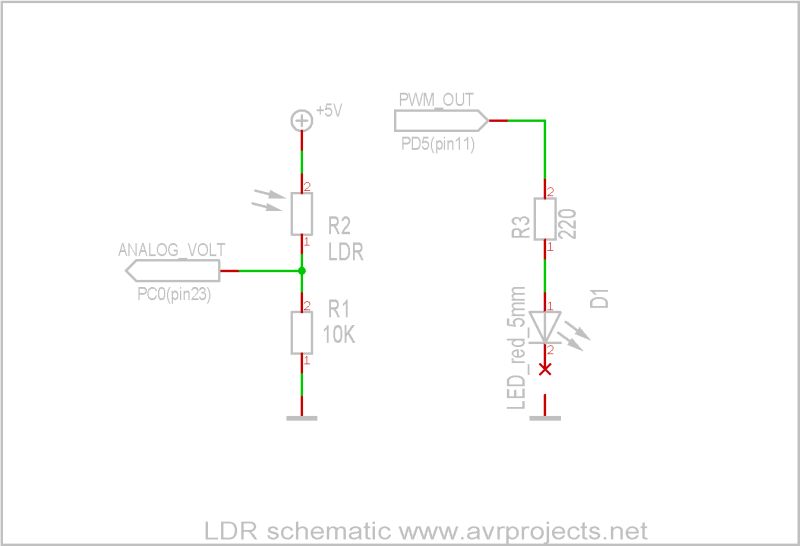
Circuit example
In this example the sensor is connected to the power (5V) and to a pull down resistor to ground. Then the point between the pulldown resistor and the LDR is connected to the analog input of a microcontroller.
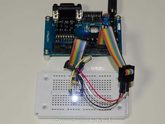
The analog voltage reading is used to determine if the LED is on or off. The darker it is, the LED will be on, if it is light the led will be off. The LED has to be connected to a ouput pin, port PB0 of the ATmega328.In the example the ATMega328 board is used. The circuit can be build on a breadboard.
For more detail: Photocell or LDR
- What is a photocell?
A photocell or photo resistor is a Light Dependent Resistor (LDR) that detects light. - How does an LDR work?
An LDR changes its resistive value depending on how much light shines on it; resistance drops when light falls on the sensor. - Can I use an LDR to determine precise light levels?
No, they are very inaccurate with variations of 50% or higher, so they should only be used to determine basic light changes. - What is the resistance range of an LDR?
Resistance can be as much as 10Mohm in the dark and drop to 1Kohm when light increases. - Which light wavelengths is the photocell most sensitive to?
The photocell is most sensitive between green light at 400nm and red light at 700nm. - How do you test a photocell with a multimeter?
Connect the multimeter in resistance-measurement mode to the two leads and observe changes while shining light or shading the sensor. - What power source is used in the circuit example?
The sensor is connected to 5V power in the provided example. - How is the LED controlled in the circuit?
The analog voltage reading determines if the LED is on or off; the LED turns on when it is dark and off when it is light.