
Summary of Password Protected BT136 Triac based Keypad Controlled Wireless Home Automation System with ATmega32 using 433MHz RF-I
This article details a password-protected wireless home appliance system using an AVR ATmega32 microcontroller, a 4x4 keypad, and 433MHz RF modules. Users enter a 4-digit password on the keypad to access controls for two bulbs and two fans, with status updates shown on a 16X2 LCD. The system encodes signals via an HT12E transmitter and decodes them at the receiver using an HT12D, which drives BT136 Triacs to operate the appliances wirelessly.
Parts used in the Password Protected BT136 Triac based Keypad Controlled Wireless Home Appliances System:
- AVR ATmega32 microcontroller
- 4X4 Keypad
- Two Bulbs
- Two Fans
- 16X2 Alphanumeric LCD
- HT12E Encoder
- RF Transmitter Circuit (433MHz)
- RF Receiver Module
- HT12D Decoder
- BT136 Triac Driver
In this project, we will learn How to design a Password Protected BT136 Triac based Keypad Controlled Wireless Home Appliances System with AVR ATmega32 microcontroller using 433MHz RF Part-I. Here, we will use the 4X4 keypad as the input device to enter the password and to control the appliances i.e 2 bulbs and 2 fans. Also, we will display the status of each appliance in the 16X2 alphanumeric LCD. The password is a 4 digit number. In our case the password is “1234” which can be changed in the program. To gain access of the system, the user has to enter the correct password.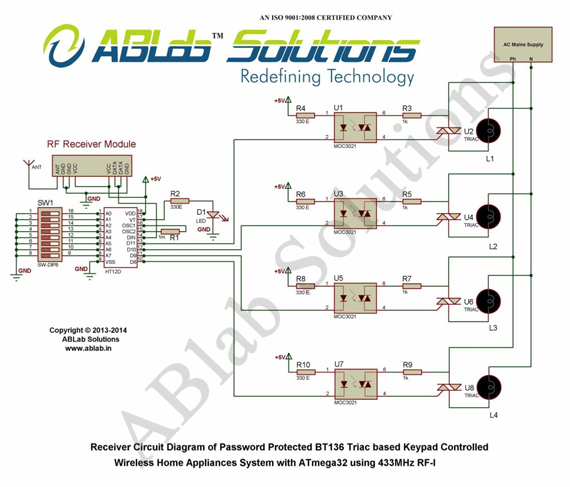
The ATmega32 microcontroller will read the 4X4 keypad. First the user will enter the 4 digit password each digit of which will be displayed in a 16X2 alphanumeric LCD as star(*). The microcontroller will compare the entered password with the set password. The system will ask to enter password till the correct password is entered by the user. After the correct password is entered, the microcontroller will read the appliance control signal from 4X4 keypad and it will process the control signal to know which key of the 4X4 keypad is pressed. After knowing which key of the 4X4 keypad is pressed, the ATmega32 microcontroller will send the required 4 bit signal to the HT12E encoder of RF transmitter circuit. The HT12E will encode the 8 bit address and 4 bit data given to it and then it will transmit the encoded signal serially to the RF module. The RF module will transmit the encoded data and address wirelessly. The microcontroller will also display the change in the status of the appliance in the 16X2 alphanumeric LCD.
At the receiver end, the RF receiver module will receive the encoded 4 bit data and 8 bit address. Then, it will transmit the encoded signal serially to the HT12D decoder which will decode the received signal to 8 bit address and 4 bit data. After decoding, the HT12D will compare the received 8 bit address with its local 8 bit address. If the received address and the local address are same, then the received 4 bit data is sent to its output pins else the received data is discarded. The 4 bit output of HT12D is sent to the BT136 Triac Driver to turn on and off appliances.
Here, we will use 2 keys of the Keypad to control one appliance. One key will be used to turn on and the other key will be used to turn off the appliance. So, for four appliances, we will use 8 keys of the keypad. Apart from these 8 keys, we will use 2 more keys to turn on and off all appliances at a time. Now, press different keys of the 4X4 keypad and control your appliances.
For more detail: Password Protected BT136 Triac based Keypad Controlled Wireless Home Automation System with ATmega32 using 433MHz RF-I
- How is the password entered and displayed?
The user enters a 4-digit password using the 4X4 keypad, where each digit appears as a star (*) on the 16X2 alphanumeric LCD. - Can the default password be changed?
Yes, the default password of 1234 can be changed within the program code. - What happens if the wrong password is entered?
The system will ask the user to enter the password again until the correct one is provided. - How are appliance control signals transmitted?
The microcontroller sends a 4-bit signal to the HT12E encoder, which adds an 8-bit address and transmits the encoded data wirelessly via the RF module. - How does the receiver verify the signal?
The HT12D decoder compares the received 8-bit address with its local address; if they match, it passes the 4-bit data to the output pins. - Which components drive the appliances at the receiver end?
The 4-bit output from the HT12D is sent to the BT136 Triac Driver to turn the appliances on or off. - How many keys are required to control all appliances?
Eight keys are used to control individual appliances (two per device), plus two additional keys to turn all appliances on or off simultaneously. - Does the system display appliance status changes?
Yes, the microcontroller displays any changes in appliance status on the 16X2 alphanumeric LCD.