
Summary of An isolated analog output for Arduino Uno
This project shows how to create a fully isolated Arduino analog output by averaging a PWM pin with a low-pass filter and isolating the digital PWM with an optocoupler. Using Arduino Uno (ATmega328) PWM (pin 9 used here) and Timer1 prescalers, you can adjust PWM frequency and, with appropriate filtering and reference changes, obtain a stable 0–5 V (or higher) isolated analog output for small automation systems, improving protection against EMI, surges, and ground potential differences.
Parts used in the Isolated Arduino Analog Output:
- Arduino PWM Uno (or ATmega328-based system)
- Optocoupler (for isolating PWM digital signal)
- Low-pass filter components (resistor and capacitor)
- Power supply / reference voltage source (0–5 V or higher)
- Wiring/connectors
This project uses the Arduino PWM Uno or other systems to realize a fully isolated analog output with a range of 0-5 volts or more, changing only the reference voltage.
Introduction
This project completes the series of my articles about the Arduino analog I/O with the aim to use it as a controller of small automation systems.
In control systems of the industrial plants it is always advisable to isolate both the inputs and the outputs coming from the field. This prevents disturbances caused by power surges, lightning strikes or other EMI sources and also by ground potential differences.
Arduino Uno, or systems based on the ATmega328 chip has no a true analog output, but it may be realized using a PWM output averaged with a low-pass filter.
The use of an averaged PWM signal with 8-bit setting is not comparable with a real DAC, but in the insulation case presents undoubted advantages of simplicity since it is sufficient to use an optocoupler for isolating the PWM digital signal. Recently I designed another circuit to generate a 4-20 mA current with Arduino, that experience gave me the idea for this new project.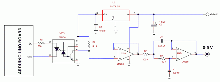
The Arduino PWM
Arduino Uno has several pins (3, 5, 6, 9, 10, and 11) that can be configured for PWM output. For this project I used pin 9 because the others were used by various devices (LCD, SD and RTC) in my Arduino system.
The PWM signal on pins D9 and D10 is generated by Timer# 1 of ATmega328. It has a prescaler which divides by 1, 8, 64, 256, 1024, controlled by the three least significant bits of the register TCCR1B. The default value of the prescaler set by the Arduino IDE is equal to Np= 64 (TCCR1B, bits 2-0= 110), which provides an output frequency:
PWM frequency = CPUClock/(2´Np´TOP) = 16000000/(2´64´255)= 490.196 Hz
Where the TOP value is he maximum Timer/Counter value.
The following table shows the frequencies generated by Timer# 1 of an Arduino Uno (Atmega 328) on pins 9 and 10, with a 16 MHz clock and in “phasecorrect PWM” mode. In this mode, the timer counts from 0 to 255 and then back down to 0.
| Prescaler divider (Np) | Prescaler code | PWM frequency |
| 1 | B001 | 31372.549 |
| 8 | B010 | 3921.569 |
| 64 | B011 | 490.196 |
| 256 | B100 | 122.549 |
| 1024 | B101 | 30.637 |
The prescaler code must be put in the three least significant bits of the register TCCR1B – Timer/Counter1 Control Register B. For example, to generate a PWM of 3921 Hz, the following instruction must be inserted in the setup function:
For more detail: An isolated analog output for Arduino Uno
- Can Arduino Uno produce a true analog output?
No; Arduino Uno does not have a true analog output, but a PWM output averaged with a low-pass filter can be used. - How is isolation achieved for the PWM-based analog output?
Isolation is achieved by using an optocoupler to isolate the PWM digital signal from the field side. - Which Arduino pins generate PWM from Timer1?
Pins D9 and D10 generate PWM driven by Timer1 on the ATmega328. - Why is isolating field inputs and outputs recommended?
Isolation prevents disturbances from power surges, lightning, EMI sources, and ground potential differences. - What PWM frequency does Timer1 produce with the default prescaler?
With the default prescaler Np = 64, Timer1 in phase-correct PWM mode produces about 490.196 Hz on pins 9 and 10. - How can the PWM frequency be changed on Timer1?
By changing the prescaler bits (three least significant bits) in the TCCR1B register to select dividers 1, 8, 64, 256, or 1024. - What is the formula for PWM frequency in this mode?
PWM frequency = CPUClock/(2 × Np × TOP), where TOP is 255 in phase-correct PWM mode. - Which prescaler gives approximately 3921.569 Hz PWM frequency?
The prescaler divider Np = 8 produces about 3921.569 Hz on Timer1.
