
Summary of 5V Regulator Cap for 9V battery
### Summary The article describes a DIY 5V linear voltage regulator designed to power projects using a 9V battery. This portable solution serves as an alternative to larger benchtop power supplies. The circuit includes reverse polarity protection, input/output capacitors for stability, and a flashing LED indicator to show power status and save energy. The project utilizes two PCBs: one housing the regulator components and battery snap, and another featuring the power switch and connection headers.
Parts used in the 5V Regulator Cap for 9V Battery:
- D1: Small signal diode
- C1: 0.1 µF capacitor (battery input)
- C2: 0.1 µF capacitor (regulator output)
- C2bulk: 1 µF or larger capacitor (regulator output)
- IC1: Voltage regulator (TO-92 package)
- R1: Current limiting resistor (or wire if using flashing LED)
- LED1: Flashing LED with concave lens
- Power switch
- Battery snap connector
- Two PCB boards
- Interconnect pins or plain wire
I have a $500 Rigol DP832 programmable triple-output power supply sitting on my bench, yet I built a 5V regulator to sit atop a 9V battery for some reason. Perhaps it’s more portable, or cheap enough to toss in with the rest of the project it is powering, or maybe the bench power supply is just overkill. Or maybe, just maybe, I saw other people making them and I thought it would be cool to build myself.
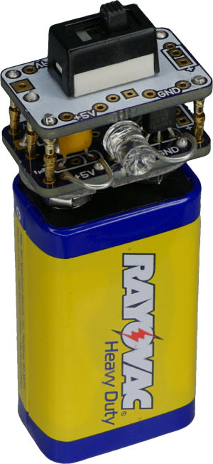
Two boards were used to enclose the circuitry and to allow the power switch to stand out on its own. Also, the board connection pins are power points. So, you can use the hookup loops, board interconnect pins, header connectors, or wire holes to connect the power supply to your project.
The circuit is not fancy. It’s just a classic linear voltage regulator.
D1: Prevents damage due to connecting the battery backwards. Any small signal diode will do, because the current output of the TO-92-sized regulator is fairly low and the voltage drop between 9V and 5V is large enough to be unaffected by the diode voltage drop.
C1: 0.1 µF capacitor on the battery input
C2: 0.1 µF capacitor on the regulator output.
C2bulk: 1 µF or larger capacitor on the regulator output. All three capacitors stabilize the regulator output as the project consumes different levels of power during operation.
IC1: The voltage regulator that converts between the unregulated 9.6 volts to 7 volts from the battery into a steady 5 V or 3.3 V or whatever is desired.
R1: Resistor that limits the amount of current provided to LED1. Usually between 220 ohms and 470 ohms. In this case, LED1 is a flashing LED that does not need a current-limiting resistor, so a wire is used instead.
LED1: Power indicator LED. This is to avoid forgetting to turn off the regulator when not in use. The regulator uses a certain amount of power even when idle.
I chose a flashing LED in this case to draw more attention to the fact that the power supply is turned on. Also, a flashing LED uses less power than a steady LED, because a flashing LED is off part of the time.
This particular LED is unusual in that it has a concave lens. Supposedly, such a shape provides a wider viewing angle. (Unfortunately, I don’t have a part number for this, as it came from a lot sale on an auction site a while ago.)
The bottom of the lower board has the battery snap. The top of the lower board has the regulator circuitry. The bottom of the upper board is empty except for circuit traces. The top of the upper board contains the power switch and connection points.
The upper and lower boards can be connected with plain wire or interconnect pins. The plain wire is permanent but inexpensive.
Read more: 5V Regulator Cap for 9V battery
- Why build a custom 5V regulator instead of using a bench power supply?
The author chose this for portability, cost-effectiveness, and because a bench supply might be overkill for small projects. - What is the function of diode D1 in the circuit?
D1 prevents damage caused by connecting the battery backwards. - Why was a flashing LED chosen for the power indicator?
A flashing LED draws less power than a steady one and provides more attention to indicate the unit is on. - Do all components require specific current-limiting resistors?
No, the flashing LED used does not need a resistor, so a wire was used instead of the typical 220 to 470 ohm resistor. - How do the capacitors stabilize the circuit?
The three capacitors stabilize the regulator output as the project consumes different levels of power during operation. - Can I connect the upper and lower boards permanently?
Yes, you can use plain wire for a permanent but inexpensive connection between the boards. - What voltage range does the regulator handle from the battery?
The regulator converts unregulated voltage ranging from 9.6 volts down to 7 volts into a steady 5 V or 3.3 V. - Is the LED part number available in the text?
No, the author does not have the part number as the LED came from a lot sale on an auction site.