
Summary of 3 Phase AC Motor Controller
This project utilizes the NXP MC3PHAC chip to create a standalone 3-phase AC motor controller generating six PWM signals and a brake signal. It operates without software coding, supporting variable speed and acceleration via potentiometers. The board features built-in fault protection, including DC bus monitoring and external fault inputs, making it ideal for integration with Intelligent Power Modules (IPMs) or IGBT/MOSFET inverters in Variable Frequency Drives (VFDs).
Parts used in the 3-Phase AC Motor Controller:
- NXP MC3PHAC Monolithic Intelligent Motor Controller IC
- Intelligent Power Module (IPM) or 3 Phase IGBT/MOSFET Inverter
- Gate Driver Circuit
- Potentiometer PR1 for Acceleration Control
- Potentiometer PR2 for Speed Control
- Dip Switch for Frequency Selection (50/60 Hz)
- Jumpers for PWM Polarity Configuration (Active Low/High)
- Connecter CN3 for External Fault Monitoring Input
- DC Bus Voltage Monitoring Circuitry
- System Fault Input Pin
This project made using MC3PHAC from NXP Semiconductor. The project generates 6 PWM signals for 3 Phase AC Motor controller. It’s very easy to make professional VFD combining with Intelligent Power Module (IPM) or 3 Phase IGBT/MOSFET with Gate driver. The board provides 6 PWM signals for the IPM or IGBT Inverter and also brake signal. Also this board works in stand-alone mode and doesn’t require any software programming/coding.
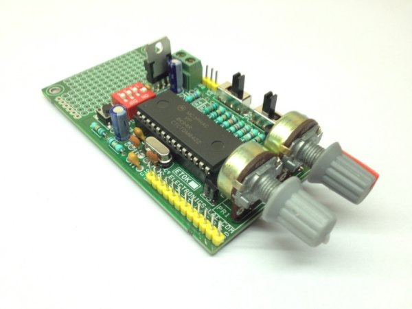
The MC3PHAC is a high-performance monolithic intelligent motor controller designed specifically to meet the requirements for low-cost, variable-speed, 3-phase ac motor control systems. The device is adaptable and configurable, based on its environment. It contains all of the active functions required to implement the control portion of an open loop, 3-phase ac motor drive. One of the unique aspects of this board is that although it is adaptable and configurable based on its environment, it does not require any software development. This makes the MC3PHAC a perfect fit for customer applications requiring ac motor control but with limited or no software resources available.
Included in the MC3PHAC are protective features consisting of dc bus voltage monitoring and a system fault input that will immediately disable the PWM module upon detection of a system fault.
All outputs are TTL signals, Input supply 5-15V DC, DC Bus voltage should be between 1.75V-4.75V, Dip switch provided to set the motor frequency 60 or 50 Hz, jumpers also helps to set the polarity of the output PWM Active Low or Active High and this helps to use this board with any kind of IPM modules since output can be set active low or high. Potentiometer PR2 helps to adjust motor speed. Refer to datasheet of the IC to change base frequency, PWM Dead Time, other possible parameters.
Speed Control — the synchronous motor frequency can be specified in real time to be any value from 1 Hz to 128 Hz by adjusting the PR2 potentiometer. The scaling factor is 25.6 Hz per volt. The SPEED pin is processed by a 24-bit digital filter to enhance the speed stability in noisy environments.
Acceleration Control — Motor acceleration can be specified in real time to be in the range from 0.5 Hz/second, ranging to 128 Hz/second, by adjusting the PR1 potentiometer. The scaling factor is 25.6 Hz/second per volt.
Fault Protection: The MC3PHAC supports an elaborate range of fault protection and prevention features. If a fault does occur, the MC3PHAC immediately disables the PWMs and waits until the fault condition is cleared before starting a timer to re-enable the PWMs. Refer to the graph in Figure 10 for the resistance value versus retry time from data sheet of the IC. Figure 10 assumes a 6.8 kΩ pull up resistor. In standalone mode, this timeout interval is specified during the initialization phase by supplying a voltage to the MUX_IN pin while the RETRY_TxD pin is being driven low. In this way, the retry time can be specified from 1 to 60 seconds, with a scaling factor of 12 seconds per volt
External Fault Monitoring: The FAULTIN pin accepts a digital signal that indicates a fault has been detected via external monitoring circuitry. A high level on this input results in the PWMs being immediately disabled. Typical fault conditions might be a dc bus over voltage, bus over current, or over temperature. Once this input returns to a logic low level, the fault retry timer begins running, and PWMs are re-enabled after the programmed timeout value is reached. FLTIN input pin 9 of the connecter CN3 should be high to bring the fault pin low for normal operation.
Read more: 3 Phase AC Motor Controller
-
Does this project require software programming?
No, the board works in stand-alone mode and does not require any software programming or coding. -
How is motor speed controlled in real time?
Speed is adjusted from 1 Hz to 128 Hz by turning the PR2 potentiometer with a scaling factor of 25.6 Hz per volt. -
Can the output polarity be changed?
Yes, jumpers are provided to set the output PWM polarity to either Active Low or Active High. -
What happens if a system fault occurs?
The MC3PHAC immediately disables the PWM module and waits until the fault clears before starting a timer to re-enable. -
How is the retry time for faults specified?
The retry time is specified during initialization by supplying voltage to the MUX_IN pin while driving the RETRY_TxD pin low. -
What is the function of the FAULTIN pin on connector CN3?
This pin accepts a digital signal for external fault monitoring; a high level immediately disables the PWMs. -
How is motor acceleration adjusted?
Acceleration is specified from 0.5 Hz/second to 128 Hz/second by adjusting the PR1 potentiometer. -
What input supply voltage is required for the board?
The board requires an input supply between 5V and 15V DC.
