
Summary of Fastest Finger First Quiz Project using ATmega16
This article details a Fastest Finger First Quiz System built around an ATmega16 microcontroller, supporting up to eight contestants. The system detects the first button press via switches, illuminates corresponding LEDs with a blinking effect, displays the winner's ID on a 4-inch seven-segment display, and triggers a buzzer. A reset button allows for subsequent rounds, while a 12V adapter and 7805 regulator provide stable power.
Parts used in the Fastest Finger First Quiz Project:
- ATmega16 Microcontroller
- Eight Input Switches
- Eight Output Indicator Lights (LEDs)
- 4 inch Seven Segment Display
- ULN2003 Driver IC
- Buzzer
- Reset Button
- 12V DC Adapter
- IC 7805 Voltage Regulator
- Diode D9
- Capacitor C1
- Diode D10
- Resistor R3
- Resistor R2
- Resistor R1
- Transistor Q1
- General Purpose PCB or Basic PCB for ATmega16
- USB AVR Programmer
Most of you must have watched quiz games in TV shows or at your schools where few contestants are required to press a switch if they know the answer to the question. An electronic system is required to find out exactly which one of then pressed the button first. This type of electronic system can be easily designed with an AVR microcontroller like ATmega16. We will make a system that will support upto 8 contestants so we will need eight inputs. These inputs are switches that would be placed on each contestant’s table. We also need eight outputs, these will be the indicator lights put on the tables. These will indicate which one of them pushed the button first. Since we are using a programmable IC we will make this more fancy by adding a blinking effect to these lamps. So they will not simply glow as in other projects but also they will blink to attract attention!
To make this even fancier, we will also add a seven segment display to numerically show the id of contestant who pressed the button first. We will be using a 4 inch display that runs off 12v so we need a ULN2003 to drive them.
We also have a buzzer in this system which beeps when any button is pressed. To use the system next time, reset button must be pressed.
Circuit Diagram
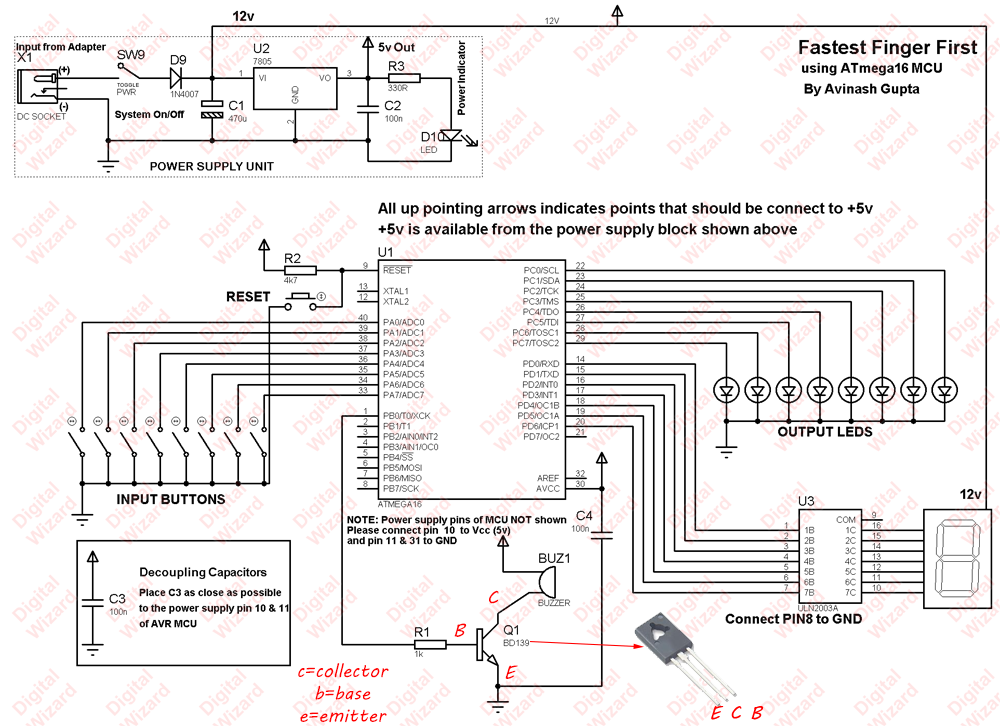
The power supply units takes input from a 12V DC adapter and convert it to 5v supply for microcontroller and other ics. Diode D9 prevents burning of 7805 ic from reverse voltage. Capacitor C1 filters ripple from power supply, IC7805 is the voltage regulator IC. Diode D10 is the power indicator LED and R3 limits the current to it. R2 keeps the RESET pin of MCU pulled up for normal operation while RESET push button can be used to reset the MCU.
R1, Q1 forms the driver circuit for the buzzer. IC ULN2003 is used to drive the large seven segment module.
330 ohms resistors should be used in series with the output leds. These resistors are not shown in the schematic.
This circuit can be made in a general purpose PCB or a Basic PCB for ATmega16.
ATmega16 should be programmed with the HEX file given at the end of this article, the HEX file contains the program in machine language and is burned to the flash memory of ATmega16 using USB AVR Programmer.
For more detail: Fastest Finger First Quiz Project using ATmega16
- How many contestants can this system support?
The system is designed to support up to eight contestants using eight inputs and outputs. - What component drives the large seven segment module?
An ULN2003 driver IC is used to drive the 4 inch display running off 12v. - Does the indicator light simply glow or blink?
The lamps blink to attract attention rather than just glowing continuously. - What happens when any button is pressed?
A buzzer beeps when any button is pressed to signal an input event. - How do you reset the system for the next round?
The RESET push button must be pressed to reset the MCU and use the system again. - What is the function of Diode D9 in the circuit?
Diode D9 prevents burning of the 7805 IC from reverse voltage. - Which resistor limits current to the power indicator LED?
Resistor R3 limits the current to the power indicator LED D10. - What tool is required to program the microcontroller?
A USB AVR Programmer is needed to burn the HEX file into the flash memory of the ATmega16.