
Summary of Servo Motor Control by Using AVR ATmega32 Microcontroller
This article explains how to control hobby servo motors, specifically the Futaba S3003 and Vigor VS-10, using AVR microcontrollers like the ATmega32. It details the servo's feedback mechanism, wiring requirements (Red, Black, White), and the PWM signal specifications needed for precise angle positioning. The guide provides a step-by-step configuration of Timer1 on an AVR chip to generate 50Hz PWM signals, including specific register values for different angles and code examples for moving servos between positions.
Parts used in the Servo Motor Control Project:
- Futaba S3003 Servo Motor
- Vigor VS-10 High Torque Servo
- AVR Microcontroller (ATmega32 or ATmega16)
- 16 MHz Crystal Oscillator
- Low Cost AVR Development Board or xBoard v2
- USB AVR Programmer v2.0
- 5V Regulated Power Supply
Servo motors are a type of electromechanical actuators that do not rotate continuously like DC/AC or stepper motors, rather they used to position and hold some object. They are used where continuous rotation is not required so they are not used to drive wheels (unless a servo is modified). In contrast they are used where something is needed to move to particular position and then stopped and hold there. Most common use is to position the rudder of aircrafts and boats etc. Servos can be used effectively here because the rudder do not need to move full 360 degrees nor they require continuous rotation like a wheel. The servo can be commanded to rotate to a particular angle (say 30) and then hold the rudder there. Servos also employs a feedback mechanism, so it can sense an error in its positioning and correct it. This is called servomechanism. So if the air flow exerts pressure on rudder and deflects it the servo will apply force in opposite direction and try to correct the error. Say if you ask servo to go and lock itself to 30 degrees and then try to rotate it with your hand, the servo will try hard and its best to overcome the force and keep servo locked in its specified angle.
Servos are also used to control the steering of RC cars, robotics arms and legs.
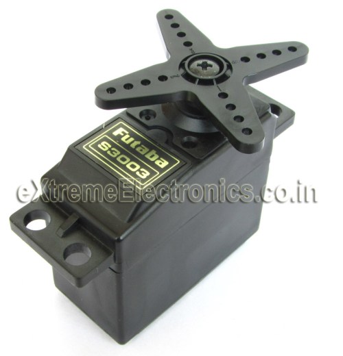
Their are many types of servos but here we will concentrate on small hobby servos. Hobby servo has motor and its control mechanism built into one unit. They have 3 wire connector. One is for positive supply other for ground and the last one for control signal. The image below shows a common hobby servo from Futaba, its S3003.
Futaba S3003 wiring.
- RED -> Positive supply 4.8v to 6v
- BLACK -> GND
- WHITE -> Control Signal.
Controlling a Servo Motor.
Controlling a servo is easy by using a microcontroller, no external driver like h-bridge etc are required. Just a control signal is needed to be feed to the servo to position it in any specified angle. The frequency of the control signal is 50hz (i.e. the period is 20ms) and the width of positive pulse controls the angle.
Servo Motor Control Signal. |
For Futaba 3003 servos, I found out the following timings. The relation between the width of pulse and servo angle is given below. Note that these servos are only capable of rotating between 0 and 180 degrees.
- 0.388ms = 0 degree.
- 1.264ms = 90 degrees. (neutral position)
- 2.14ms = 180 degrees.
Controlling Servo Motors with AVR Microcontrollers.
You can use the AVR micro controllers PWM feature to control servo motors. In this way the PWM with automatically generate signals to lock servo and the CPU is free to do other tasks. To understand how you can setup and use PWM you need to have basic understanding of hardware timers and PWM modules in AVR. The following articles may be of great help.
- Introduction to PWM
- Generating PWM Signals by using AVR Timers.
- Introduction to AVR Timers.
- Timers in compare Mode.
Here we will use AVR Timer1 Module which is a 16bit timer and has two PWM channels(A and B). The CPU frequency is 16MHz, this frequency is the maximum frequency that most AVRs are capable of running. And so it is used in most development board like Low Cost AVR Development Board and xBoards. We chose the prescaler as 64. So the timer will get 16MHz/64 = 250khz (4 uS period). We setup Timer Mode as Mode 14.
Timer Mode 14 features
- FAST PWM Mode
- TOP Value = ICR1
So the timer will count from 0 to ICR1(TOP Value). The formula for PWM frequency and calculation for TOP value is given below
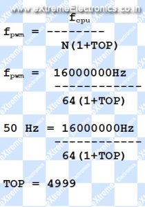
So we set up ICR1A=4999, this gives us PWM period of 20ms (50 Hz). Compare Output Mode is set by correctly configuring bits COM1A1,COM1A0 (For PWM Channel A) and COM1B1,COM1B0(For PWM Channel B)
COM1A1 = 1 and COM1A0=0 (for PWM Channel A)
COM1B1 = 1 and COM1B0=0 (for PWM Channel B)
The above settings clears the OC1A (or OC1B) pin on Compare Match and SET ( to high) at BOTTOM. The OC1A and OC1B pins are the PWM out pin in ATmega16/ATmega32 chips. This settings gives us NON inverted PWM output.
Now the duty cycle can be set by setting OCR1A and OCR1B registers. These two register controls the PWM high period. Since the period of timer is 4uS (remember 16Mhz divided by 64?) we can calculate values required for following servo angles.
- Servo Angle 0 degrees require pulse width of 0.388ms(388uS) so value of OCR1A = 388us/4us = 97
- Servo Angle 90 degrees require pulse width of 1.264ms(1264uS) so value of OCR1A = 1264us/4us = 316
- Servo Angle 180 degrees require pulse width of 2.140ms(2140uS) so value of OCR1A = 2140us/4us = 535
If you are using Vigor VS-10 (High Torque Servo) then you need the following values.
- Set OCR1A=180 for 0 degree.
- Set OCR1A=415 for 90 degree.
- Set OCR1A=650 for 180 degree.
In this way you can calculate the value of OCR1A( or OCR1B for second servo) for any angle required. We can see that the value of OCR1x varies from 97 to 535 for servo angle of 0 to 180 degrees.(180 to 650 in case of Vigor VS-10)
Complete AVR ATmega32 Code for Servo Motor Control Demo.
The demo program given below shows how to use servo motors with AVR microcontroller. The job of the program is very simple, it starts by initializing the timer and pwm. Then it locks the servo at 0 degree, then moves it to 90 degree and wait for australian pokies some time, then similarly goes to 135 degree and finally to 180 degrees. The process is repeated as long as powered.
Some Parameter for proper working of program.
- LOW Fuse = 0xFF and HIGH Fuse = 0xC9
- Crystal Frequency = 16MHz.
- Servo Motor is branded Futaba S3003.
- MCU is ATmega32 or ATmega16.
/******************************************************************************

Program to demonstrate the use servo motors with AVR Microcontrollers.

For More Details Visit: http://www.eXtremeElectronics.co.in

Copyright (c) 2008-2010
eXtreme Electronics, India

Servo Motor: Futaba s3003
Servo Control PIN (white): To OC1A PIN
Crystal: 16MHz
LOW Fuse: 0xFF
HIGH Fuse: 0xC9

Compiler:avr-gcc toolchain
Project Manager/IDE: AVR Studio

                                     NOTICE
                           --------
NO PART OF THIS WORK CAN BE COPIED, DISTRIBUTED OR PUBLISHED WITHOUT A
WRITTEN PERMISSION FROM EXTREME ELECTRONICS INDIA. THE LIBRARY, NOR ANY PART
OF IT CAN BE USED IN COMMERCIAL APPLICATIONS. IT IS INTENDED TO BE USED FOR

HOBBY, LEARNING AND EDUCATIONAL PURPOSE ONLY. IF YOU WANT TO USE THEM IN
COMMERCIAL APPLICATION PLEASE WRITE TO THE AUTHOR.


WRITTEN BY:
AVINASH GUPTA
[email protected]

*******************************************************************************/
#include <avr/io.h>

#include <util/delay.h>

//Simple Wait Function
void Wait()
{
   uint8_t i;
   for(i=0;i<50;i++)
   {
      _delay_loop_2(0);
      _delay_loop_2(0);
      _delay_loop_2(0);
   }

}

void main()
{
   //Configure TIMER1
   TCCR1A|=(1<<COM1A1)|(1<<COM1B1)|(1<<WGM11);        //NON Inverted PWM
   TCCR1B|=(1<<WGM13)|(1<<WGM12)|(1<<CS11)|(1<<CS10); //PRESCALER=64 MODE 14(FAST PWM)

   ICR1=4999;  //fPWM=50Hz (Period = 20ms Standard).

   DDRD|=(1<<PD4)|(1<<PD5);   //PWM Pins as Out

   while(1)
   {

      OCR1A=97;   //0 degree
      Wait();

      OCR1A=316;  //90 degree
      Wait();

      OCR1A=425;  //135 degree

      Wait();

      OCR1A=535;  //180 degree
      Wait();
   }
}
Hardware
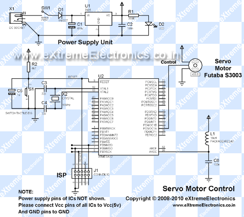
You need a basic avr circuit with 5v regulated supply, 16 MHz crystal and proper reset circuit. All these are present in most common development boards.
|
AVR ATmega32 Controlling a Futaba Servo Motor. |
If you have development boards like Low Cost AVR Development Board or xBoard v2. Then you just need to add the servo motor. Connect RED wire of servo to 5v, BLACK wire to GND and the WHITE wire to OC1A PIN.
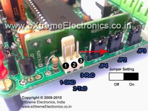
The RED Arrow Show the Position of OC1A pin on xBoard v2.0
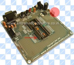
The RED Arrow Show the Position of OC1A pin.
OC1A PIN is multiplexed with PD5 GPIO pin, that’s why the Low Cost AVR Development Board it is Marked as PD5. The RED Circle in above image is where you can find the 5v and GND supplies. So adding a servo in development board is very easy.
Downloads
- Source Code.
- Complete AVR Studio Project For ATmega16(VS-10 Servo).
- HEX File for ATmega32.
- HEX File for ATmega16 (VS-10 Servo).
- HEX File for ATmega32 (VS-10 Servo).
- Only Servo.c file
- Proteus Simulation for quick testing
NOTE: HEX File can be uploaded to the boards by using a ISP Programmer like the USB AVR Programmer v2.0
Videos
The video demo of above program.
Using VS-10 High Torque Servo
Read More: Servo Motor Control by Using AVR ATmega32 Microcontroller
- How do servo motors differ from DC or stepper motors?
Servo motors are designed to position and hold objects at specific angles rather than rotating continuously. - What is the frequency of the control signal required for these servos?
The control signal frequency is 50Hz, which corresponds to a period of 20ms. - Which pins on the Futaba S3003 connect to positive supply and ground?
The Red wire connects to positive supply (4.8v to 6v) and the Black wire connects to GND. - Does controlling a servo require an external driver like an H-bridge?
No, a microcontroller can control the servo directly by feeding it a control signal without external drivers. - What timer mode is used to generate the PWM signal in this project?
Timer Mode 14 (FAST PWM Mode) with TOP Value set to ICR1 is used. - What prescaler value is selected for the 16MHz CPU frequency?
A prescaler of 64 is chosen, resulting in a timer clock of 250kHz. - What OCR1A value sets the servo to 90 degrees for a Futaba S3003?
An OCR1A value of 316 sets the servo to the 90-degree neutral position. - Can the same code be used for the Vigor VS-10 servo?
No, the Vigor VS-10 requires different OCR1A values such as 415 for 90 degrees instead of 316. - Which pin on the ATmega32 is used for the PWM output in this setup?
The OC1A pin, which is multiplexed with PD5 GPIO, is used for the PWM output.
