Summary of FREQUENCY METER CIRCUIT LCR METER ATMEGA328
This article describes building an LC meter and frequency meter using an ATmega328P (Arduino) and a comparator-based LC oscillator. The oscillator frequency shifts with added L or C, and the MCU measures frequency to compute inductance or capacitance. A reed relay switches between LC and direct frequency modes, and a Schmitt-trigger conditions the signal. Calibration compensates for stray L/C by none-load readings. The design measures inductance from nH to H and capacitance from pF to tens of nF. Code and libraries are provided for frequency measurement and display updates.
Parts used in the AVR LC Meter:
- ATmega328P microcontroller (Arduino compatible)
- Comparator (LM339 used in article)
- Pull-up resistor 3K (on comparator output pin 1)
- Feedback resistor 100K (on comparator)
- Reed relay (to switch between LC and frequency modes)
- Schmitt trigger stage (implemented with second comparator)
- Precision reference inductance L0
- Precision reference capacitance C0
- Test leads/probes for DUT (device under test)
- Display (updated via Arduino code)
- Supporting passive components (wires, connectors, resistors, capacitors)
I have been thinking about building an LC meter for a while since I do not have a multimeter that is capable of measuring inductance and while the multimeters I have can measure capacitance, they are not able to give accurate readings for small capacitance in the range of several pF’s.
There are quite a few good articles on how to build LC meters using PIC MCUs (like the ones here: 1, 2, 3), but instructions on how to build one with an ATmega MCU are few and far in between, although the basic principle is largely the same. So I decided to write this article on how to build an LC meter using an ATmega328p chip and Arduino libraries.
A typical LC meter is nothing but a wide range LC oscillator. When measuring an inductor or capacitor, the added inductance or capacitance changes the oscillator’s output frequency. And by calculating this frequency change, we can deduce the inductance or capacitance depending on the measurement.
The following schematic shows the comparator based LC oscillator I used in the LC meter. The oscillator portion is quite standard. Most of the other designs I have seen use LM311 comparator. But for this type of application, any comparator capable of oscillating up to 50kHz should be more than sufficient. I happen to have some spare LM339’s lying around so I used it in the oscillator circuit.
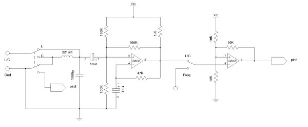
Note, there should be a 3K pull up resistor on pin 1 and the feedback resistor should be 100K instead of 10K.
Because what we are really meausring is the frequency of the oscillator, we can build a frequency meter using the same circuit at almost no additional cost. As you can see in the circuit above, a reed relay is used to switch the measurement from LC mode to frequency mode. In the schematics above, the second comparator forms a Schmitt trigger to condition the input waveform so that the frequency measurement can be made more accurate. When in the LC mode, the frequency output from the first comparator is simply feed through the Schmitt trigger. The output frequency is determined by

 LC
LC where
and
Choosing a high accuracy L0 and C0 helps improve the accuracy of the meter.
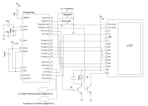
Here’s the MCU side of the schematics:
This circuit is capable of measuring inductance in a wide range, from a few nH all the way up to a few Henrys. For capatance measurement, I have found that it is most suitable for measurement from a few pF to tens of nF. You maybe able to measure slightly larger capacitors if they have a high ESR rating. But this range limit in capacitance measurement should not be an issue as what we care most about is the accuracy in the pF range.
I used this frequency library for the frequency measurement. By default, the display is updated every second. This mode provides the most accurate result. You can shorten this update interval easily, but the measurement accuracy will be reduced.
The Arduino code for this project can be downloaded here (LCFrequencyMeter.zip). This project was developed using the NetBeans IDE and you may need to adjust the included header files if you are using Arduino IDE. For more information, please see my previous article on this topic.
The calibration method I used is like this: in capacitance measurement mode, the none-load reading is used to calculate stray inductance (assume that C0 is accurate) which is then used to compensate capacitance measurements. And similarly, in inductance measurement mode, we assume that L0 is accurate and the none-load reading (by shorting the test leads) is used to calculate stray capacitance which is then used to compensate inductance measurements. If you read through the code you will get a better idea on how this is done.
The following picture shows the capacitance reading when using this meter to measure a known 2.22nF capacitor:
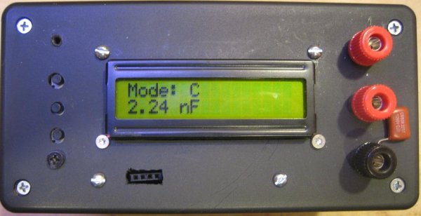
Capacitance Measurement
And this picture shows the LC meter in inductance mode, measuring a small inductor:

Inductance Measurement
Here is a picture showing frequency measurement. The frequency source is a 555 timer generated square wave:
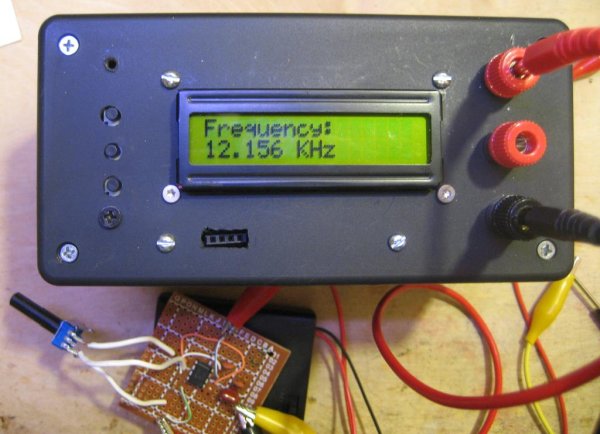
Frequency Measurement
Within a selected mode, the display is auto ranged for the components/frequencies under measurement.
- What is the basic principle behind the LC meter?
The meter is a wide range LC oscillator whose output frequency changes when the measured inductance or capacitance is added, and the MCU measures that frequency to compute L or C. - Which microcontroller is used in this project?
An ATmega328P chip (Arduino compatible) is used. - What comparator was used for the oscillator in the article?
The author used LM339 comparators for the oscillator and Schmitt trigger stage. - How is the meter switched between LC measurement and frequency measurement?
A reed relay is used to switch measurement from LC mode to direct frequency mode. - What frequency library was used for measurement?
The author used an existing frequency library referenced in the article for frequency measurement. - What measurement ranges does the circuit support?
Inductance: from a few nH up to a few H; Capacitance: from a few pF to tens of nF. - How often does the display update by default?
By default the display is updated every second for best accuracy. - How is calibration performed?
For capacitance mode, a no-load reading is used to calculate stray inductance assuming C0 is accurate; for inductance mode, a shorted no-load reading is used to calculate stray capacitance assuming L0 is accurate.