Summary of PNP Transistor – How Does It Work?
This article explains PNP transistor operation, contrasting it with NPN transistors by noting reversed current flow. It details how a 0.7V base voltage lower than the emitter activates the device, enabling current from emitter to collector. A practical example demonstrates designing a dark-activated LED circuit using these components.
Parts used in the PNP Transistor Circuit:
- PNP transistor
- LED
- Resistor
- Power source
The PNP transistor is a mystery to many. But it doesn’t have to be. If you want to design circuits with transistors, it’s really worth knowing about this type of transistor.
For example: Want to automatically turn on a light when it gets dark? The PNP transistor will make this easy for you.
In my article how transistors work, I explained how a standard NPN transistor works. If you haven’t already, I’d really urge you to read that article first.
If you understand the NPN transistor, it will make it easier to understand the PNP transistor. They work pretty much in the same way, with one major difference: The currents in the PNP transistor flow in the opposite directions of the currents in the NPN transistor.
Note: This topic is much easier with an understanding of current flow and voltages.
How PNP Transistors Work
The PNP transistor has the same leg names as the NPN:
- Base
- Emitter
- Collector
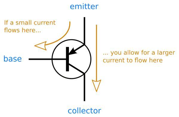
A PNP transistor will “turn on” when you have a small current running from emitter to base of the transistor. When I say “turn on”, I mean that the transistor will open up a channel between emitter and collector. And this channel can carry a much larger current.
To get current running from emitter to base, you need a voltage difference of about 0.7V. Since the current goes from emitter to base, the base needs to be 0.7V lower than the emitter.
By setting the base voltage of a PNP transistor to 0.7V lower than the emitter, you “turn the transistor on” and allow for current to flow from emitter to collector.
I know this can sound a bit confusing, so read on to see how you can design a circuit with the PNP transistor.
Example: PNP Transistor Circuit
Let’s see how to create a simple PNP transistor circuit. With this circuit you can use to turn on an LED when it gets dark.
Step 1: The Emitter
First of all, to turn on the PNP transistor, you need the voltage on the base to be lower than the emitter. For a simple circuit like this, it’s common to connect the emitter to the plus from your power source. This way, you know what voltage you have on the emitter.
Step 2: What You Want To Control
When the transistor turns on, the current can flow from the emitter to the collector. So, let’s connect what we want to control: An LED. Since an LED should always have a resistor in series with it, let’s add a resistor too.
Read more: PNP Transistor – How Does It Work?
- How does a PNP transistor turn on?
A small current running from emitter to base turns the transistor on. - What voltage difference is needed to activate the base?
The base needs to be 0.7V lower than the emitter. - Can you use a PNP transistor to control an LED?
Yes, you can create a circuit to turn on an LED when it gets dark. - Where should the emitter be connected in a simple circuit?
It is common to connect the emitter to the plus from your power source. - Does an LED need a resistor in this project?
An LED should always have a resistor in series with it. - What is the main difference between NPN and PNP currents?
The currents in the PNP transistor flow in the opposite directions of the currents in the NPN transistor. - What happens when the PNP transistor opens its channel?
The transistor allows for a much larger current to flow from emitter to collector. - Why is understanding NPN helpful for learning PNP?
They work pretty much in the same way, making prior knowledge useful.