Summary of STRAIN GAUGE SENSOR AMPLIFIER OR SINGLE SUPPLY INSTRUMENTATION AMPLIFIER
This project is a single-supply instrumentation amplifier featuring an onboard bridge configuration and a 2.5V precision reference, ideal for thermocouples, ECGs, pressure sensors, and RTDs. Built around the INA333 micropower zero-drift chip and REF5025AID voltage reference, the board easily switches between strain gauge and general instrumentation modes. It operates on 5V DC, offering high input impedance and adjustable gain to accurately measure resistance variations in bridge circuits with minimal error.
Parts used in the Strain Gauge Amplifier:
- INA333 micropower instrumentation amplifier
- REF5025AID precision reference voltage chip
- 120 Ohms Strain Gauge sensor
- R4, R5, and R9 (120 Ohms bridge resistors)
- R3 (100 Ohms gain setting resistor)
- R1, R11, and R12 (Common mode resistors)
- D1 Power LED
- J1 PCB Jumper
- CN1 Supply input connector
- CN2 Sensor connection connector
This is a new project, a single supply instrumentation amplifier with onboard bridge configuration, and a 2.5V precision reference voltage chip. The project can be configured for applications such as thermocouple amplifier, bridge amplifier, ECG amplifier, pressure sensors, medical instrumentation, portable instrumentation, RTD sensor amplifier. The project is based on INA333 micropower, zero drift, rail to rail out instrumentation amplifier chip. REF5025AID chip provides a precise 2.5V reference voltage. The board can be configured as an instrumentation amplifier or as a strain gauge amplifier with few easy changes.
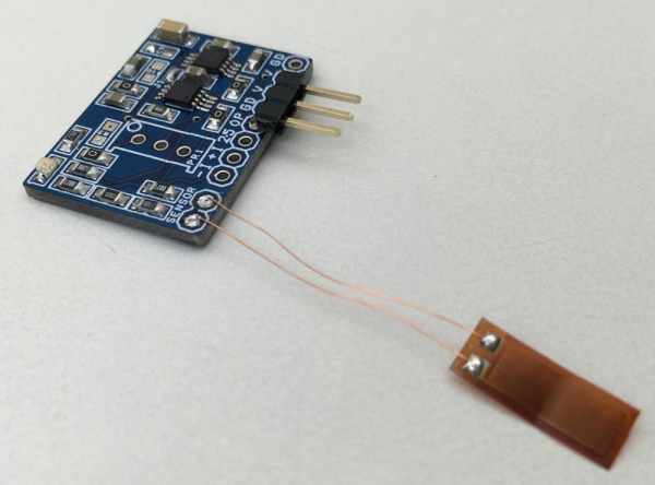
STRAIN GAUGE AMPLIFIER
The circuit shown here is a simple example of a Strain Gauge Amplifier in a bridge configuration, this strain gauge circuit accurately measures the resistance of a strain gauge sensor placed in a bridge configuration. The resistance of the strain gauge sensor varies with applied force, change in resistance is directly proportional to how much strain the sensor is experiencing due to the force applied. Changes in the strain gauge resistance create a differential voltage that is amplified by an instrumentation amplifier INA333. The amplifiers have very high input impedance and therefore introduce negligible error with respect to the bridge resistance. The output voltage of the instrumentation amplifier will be depending on the sensor’s value and variation in resistance value. The bridge excitation voltage and instrumentation amplifier reference voltage 2.5V are supplied using the REF5025. A reference voltage at mid-supply (5V DC) biases the output voltage of the instrumentation amplifier to allow differential measurements in the positive and negative direction. The common mode resistors, R1, R11 and R12, have two main functions; limit the current through the bridge and set the common mode of the instrumentation amplifier. I have used 120 Ohms Strain Gauge sensor and thus I have chosen bridge resistors R4, R5, and R9 also 120 Ohms to match the sensors impedance. Matching the bridge resistors with the strain gauge resistance produces a 0 V differential bridge voltage when the strain gauge resistance is at its nominal value. It is advisable to use very low tolerance resistors to minimize the offset and gain error due to the bridge resistors. Operating power supply 5V DC, D1 power LED, J1 PCB jumper closed. CN2 sensor connection, CN1 supply input, and sensor output, R3 100 Ohms resistor set the gain of Amplifier to approx. 1001.
FEATURES
- Power Supply 5V DC
- Output 230mV to 4.7V DC
- Strain Gauge Nominal Resistance 120 Ohms
- Stain Gauge Resistance Variation 115 Ohms to 125 Ohms
- Sensor Gauge Factor 5%
- Bridge Excitation Voltage and Reference Voltage 2.5V DC
- PCB Dimensions 26.99 x 19.21 mm
Read more: STRAIN GAUGE SENSOR AMPLIFIER OR SINGLE SUPPLY INSTRUMENTATION AMPLIFIER
- What chips form the core of this amplifier project?
The project uses the INA333 micropower zero-drift instrumentation amplifier and the REF5025AID precision reference voltage chip. - Can this board be configured for different applications?
Yes, it can be set up as an instrumentation amplifier or a strain gauge amplifier with few easy changes. - How does the circuit measure the strain gauge resistance?
Changes in resistance create a differential voltage that is amplified by the INA333 due to its very high input impedance. - What provides the bridge excitation and reference voltage?
The REF5025 supplies a precise 2.5V reference voltage and bridge excitation voltage. - Why are common mode resistors R1, R11, and R12 used?
They limit current through the bridge and set the common mode of the instrumentation amplifier. - What value were the bridge resistors chosen to match the sensor?
R4, R5, and R9 were chosen as 120 Ohms to match the nominal resistance of the 120 Ohm strain gauge sensor. - How is the gain of the amplifier determined?
A 100 Ohms resistor labeled R3 sets the gain of the amplifier to approximately 1001. - What power supply is required for operation?
The board requires a 5V DC operating power supply.