
Summary of A DIY FLUXGATE MAGNETOMETER BASED CURRENT PROBE
This article describes a sensitive, home-made current probe utilizing a Texas Instruments fluxgate magnetometer-on-a-chip. Unlike traditional methods requiring circuit interruption and known resistors, this isolated sensor measures DC to 20kHz currents ranging from single-digit microamps to 10mA without intruding on the circuit ground.
Parts used in DIY Fluxgate Magnetometer Based Current Probe:
- Fluxgate magnetometer-on-a-chip
- Evaluation board
- Analog electronics components
- Digital electronics components
- Mu-metal (noted as hard-to-find for traditional builds)
- Core material (demonstrated with Lego wheel tyre)
- Excitation windings
- Sense windings
Introduction
Current measurement can be really awkward when working with circuits. Voltage measurements are (usually) straightforward, but when it comes to current measurements the story is different. One typical approach is to insert a known resistance by breaking the circuit, and then measuring the voltage across it. This is difficult if one end of the resistor is not at ground potential, because oscilloscope probes are (usually) designed with the ground leads all connected together, and it will damage things if the grounds of different channels on the oscilloscope are connected to different parts of the circuit.
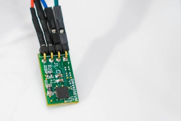
This project describes a very sensitive home-made current probe that doesn’t require a known resistance to be inserted. It has not been fully characterized but the initial results are reasonably promising. It was tested at currents of the order of single-digit microamps up to 10mA (it can be assembled for higher current ranges if desired), and it functions from DC to around 20kHz, and is fully isolated.
It is based around a very exotic magnetic field sensor known as a fluxgate magnetometer. Ordinarily this is quite difficult to build due to the requirement for hard-to-find mu-metal and a mix of analog and digital electronics. However, Texas Instruments offers an entire fluxgate magnetometer-on-a-chip and an evaluation board. With some effort it is possible to build a current sensor or probe with it. It makes a handy test tool for measuring current in a circuit, in a less intrusive way than normal.
What is a Fluxgate Magnetometer?
There are several ways to make magnetic field sensors, and the fluxgate magnetometer offers very impressive sensitivity. There are slightly different topologies of fluxgate magnetometers, but in a nutshell they consist of windings around a core. If we use a Lego wheel tyre to act as a pretend core then ‘Excitation’ and ‘Sense’ windings can be placed around it as shown in the photo (the windings are the yellow and green wires in the photo).
Read more: A DIY FLUXGATE MAGNETOMETER BASED CURRENT PROBE
-
How does this project measure current differently than standard methods?
It uses a magnetic field sensor instead of inserting a known resistance into the circuit. -
What is the operating frequency range of this current probe?
The device functions from DC to around 20kHz. -
Can this probe be used for high current ranges?
Yes, it can be assembled for higher current ranges if desired beyond the tested 10mA. -
Does this sensor require breaking the circuit to work?
No, it does not require a known resistance to be inserted or the circuit to be broken. -
What makes building a fluxgate magnetometer difficult traditionally?
It requires hard-to-find mu-metal and a mix of analog and digital electronics. -
Is the Texas Instruments solution fully isolated?
Yes, the described project is fully isolated.
