Summary of A Moving Alarm Clock
This article describes a prototype moving alarm clock designed to force users out of bed by fleeing when they attempt to silence it. The device features a 24-hour LED display, programmable alarms, snooze functionality, and caterpillar-style wheels driven by DC motors. A proximity sensor detects user movement toward the snooze button, triggering the clock to move away. The project utilizes an ATMega microcontroller, hardware oscillators for sound, and motor control circuits with optoisolation, all powered by AA batteries.
Parts used in the Moving Alarm Clock:
- ATMega 1284p microcontroller
- 7-segment display, 4 digit
- Breadboard
- 1.5W 8 Ohm Speaker
- Pololu Carrier with Sharp GP2Y0D810Z0F Digital Distance Sensor
- 555 Timer IC
- BUZ73 Transistor
- 4N35 Optoisolator
- 1N4001 Diode
- AA Batteries
- Dagu Rover 5 Tracked Chassis
Introduction
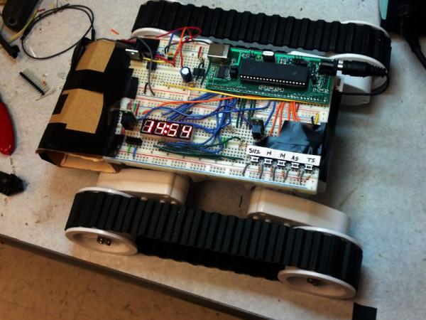
We implemented a prototype for a moving alarm clock which runs away from the user when they try to silence the alarm. It has all the features of a “regular” alarm clock: settable time and alarm, snooze, and alarm on/off. The alarm clock displays the time in 24-hour format on a LED seven-segment display. The whole unit is mounted on a chassis with caterpillar-style wheels driven by two small DC motors. A proximity sensor is mounted near the snooze button which is activated whenever the user’s finger nears the button, causing the clock to move away. It is intended to lure the user out of bed when the alarm sounds. Instead of being able to hit snooze three or four times and sleep in, the user will have to get up and chase the clock to silence it.
High-Level Design
The idea of our project rose from a common problem many college students face: ineffective alarm clocks. Regardless of how loud the alarm is, a sleepy college student can easily snooze/turn off the alarm and go back to sleep. To combat this, we wanted to design an alarm clock that would force the user to actually be somewhat alert to turn off the alarm. The end result was an alarm clock that runs away from the user when the user tries to snooze or turn off the alarm.
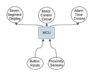
At a high level, we split our design into four major subsystems: time calculation and display, alarm tone generation, motion control and proximity sensing. Throughout our design process, we made sure to have concrete interfaces between each of the subsystems such that we could work on different subsystems concurrently and also debug more easily.
Hardware/Software Tradeoffs
While implementing our design, we had to make the decision to use either a hardware or software implementation. We made this decision by considering the factors of simplicity, flexibility, and overall performance. For example, we initially implemented the alarm tone generation in software using pulse-width modulation (PWM) to produce a sawtooth wave output directly from the microcontroller. This would then be fed to a hardware amplifier to drive the speaker. We switched to a hardware implementation when we realized that the hardware oscillator is simpler to build then the amplifier, and can drive the speaker directly. Other portions of our design (such as computing the motor control signal and calculating the time) where much more easily implemented in software with the additional benefit of being very easy to change and debug.
Existing Projects
While we did not draw inspiration from similar products for this idea, we later found out that there existed an alarm clock manufactured by NANDA Home (Clocky). It has a similar behavior to our alarm clock, so the patents that exist for this clock would be very relevant to our project should we take our project further. However, a fundamental difference between our design and Clocky is that Clocky moves and hides during the night, before the alarm goes off and then the user has to find it. Our design does not move until the user tries to silence the alarm, and then it moves away from the user.
Hardware Design
There are four main hardware components to our alarm clock: the inputs to the microcontroller (buttons, switches, and sensors), the seven-segment display, the motor drive system, and the alarm tone oscillator.
Tone Oscillator
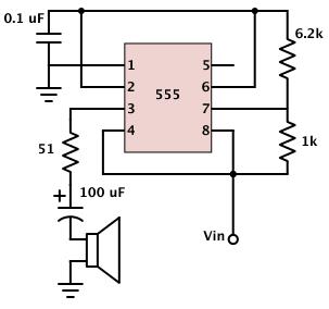
The alarm tone is generated using a hardware oscillator implemented using the 555 timer IC. The frequency is set by the two resistors and capacitor, and we tuned it to roughly 1000 Hz. The chip is not wired to VCC directly, but to an output pin on the microcontroller, which is driven high or low to turn on or turn off the oscillator, respectively. We chose this oscillator because it is stable and produces a reasonably loud alarm tone through the speaker and is low-power enough to be run directly off the microcontroller. Also, it does not require a separate audio amplifier circuit to drive the speaker.
Motor Control
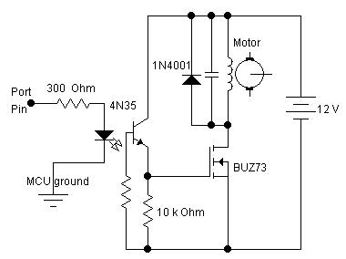
We made use of the motor control circuit from ECE 4760 lab 4. This circuit uses a transistor as a digital switch, and an optoisolator to completely isolate the microcontroller from the motor’s power supply. The microcontroller also gets its power directly from the same battery pack, so we used two large capacitors across the power supply plus a diode in series with the MCU to insulate the microcontroller against any voltage spikes generated by the motor. When we designed the motor control circuit, we also experimented with different motor speeds (changed using the motor supply voltage) to see find the optimum speed for the alarm clock. The figure below is the schematic of the motor control circuit used.
Inputs and Sensors
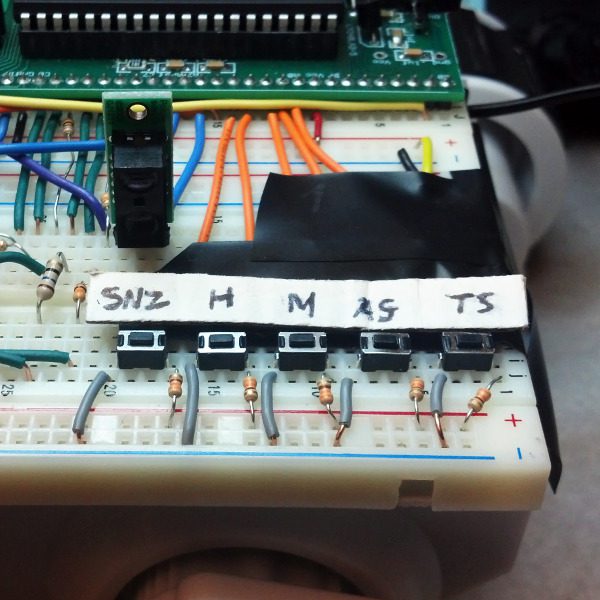
All inputs to the microcontroller (switches and buttons) were wired active low. For pushbuttons, a pull-up resistor to VCC was connected to one pin, and the other was shorted to ground. The MCU read its input from the pin connected to the pull-up resistor. It reads high, until the button is pushed, shorting it to low. We used an SPDT switch for alarm off/on.
The proximity sensors we used came in a three-pin package. The three connections were VCC, ground, and output. At any time, the sensor outputs a digital high or low depending on whether it senses an object. The sensor’s output was active low. No debouncing or filtering was necessary on its output, which was fed directly into the microcontroller.
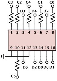
The seven-segment display we used was in a 16-pin package. It consisted of LEDs wired in such a way that each digit shared the same eight pins which control the segments. We wired the pins to the microcontroller, with resistors in series with the MCU and the diodes to keep them operating at a safe current level. We wrote a driver for the display which cycles through the digits rapidly and displays them one at a time. This is discussed in detail in the software design section.
The resistors we used to connect the display to the microcontroller are 75 ohms. Without the resistors, the microcontroller will drive too much current through the device, risking destroying the LEDs. We at first tried 100 ohm resistors, but realized these restricted the current too much and made the display too dim. We settled on 75 ohms through a process of trial and error.
Software Design
There are three main components to the software design of the alarm clock: generating the second, minute, and hour time base, responding to input from the sensors and buttons, and driving the seven-segment display that shows the current time. We used the Tiny Real Time (TRT) multitasking kernel to run each of these tasks independently and simultaneously on the microcontroller.
We generate the time base using one of the hardware timers on the ATMega microcontroller. An ISR routine is triggered by this timer at 62.5 kHz. (This rate is a remnant of when we were digitally synthesizing the alarm tone in software.) A counter counts ISR routines, and when it reaches 62,500, the current second is incremented. Similarly, when the current second reaches 59, the minute is incremented, and likewise for the hour.
Every time the minute changes, the software compares the current time with the time the alarm is set for. If the two times are equal, and the alarm is set, then it will turn on the alarm tone. When the snooze button is pressed, the alarm is re-set for 9 minutes in the future. In order to remember the original alarm time, the software keeps track of two alarm times: the time actually set by the user, and the “effective” alarm time, which is adjusted every time the user snoozes the alarm.
The alarm clock interacts with the user and the outside world through two sensors and several buttons and switches. All of the inputs are active low, and are wired to the pins of Port A on the microcontroller. The main function and entry point to the alarm clock software first performs initializations, and then enters an input-scanning loop. This loop runs as a TRT task. Debouncing is necessary for only two of the inputs: Incr Hour and Incr Min. For these buttons, a debouncing routine is run roughly every 30 milliseconds. Once a definite push is detected, the software takes action based on whether either Time Set or Alarm Set is also depressed at that instant.
| Name | Kind | Function |
| Snooze | SPST Push | If pressed when the alarm tone is playing, silence and reset the alarm 9 minutes into the future. |
| Time Set | SPST Push | When pushed, allows the Incr Hour and Incr Min buttons to advance the clock time. |
| Alarm Set | SPST Push | When pushed, shows the alarm time on the 7-seg and allows the Incr Hour and Incr Min buttons to advance the alarm time. |
| Incr Hour | SPST Push | Advances the clock hour, or the alarm hour, depending on the state of Time Set/Alarm Set. |
| Incr Min | SPST Push | Advances the clock minute, or the alarm minute, depending on the state of Time Set/Alarm Set. |
| Alarm On/Off | SPDT Toggle | Toggles whether the alarm is set, i.e. whether the tone will sound when the clock time and alarm time are the same. |
| Snooze Sensor | Proximity Sensor | Senses whether an object is present near the snooze button, and if so, turns on motion. |
Functional Listing for Alarm Clock Code (AlarmClock.c)
ISR(TIMER0_OVF_vect):
Responsible for keeping track of the current second, minute and hour. It also would call displayTime() to update the seven-segment display. It was also responsible for keeping track of the debounce time and toggling the alarm tone control signal when the alarm was ringing and the colon on the seven segment display every half second.
snooze():
Responsible for turning alarm tone off if alarm is currently ringing and updating the new alarm time to 9 minutes into the future. Triggered whenever snooze pushbutton (PIN A.4). is pushed.
turnAlarmOn():
Responsible for turning alarm functionality on (currently set alarm time will ring) and turning on alarm on indicator led on seven segment display. Triggered whenever toggle (PIN A.5) is switched to low.
turnAlarmOff():
Responsible for turning alarm functionality off (currently set alarm time won’t ring) and turning off alarm on indicator led on seven segment display. Triggered whenever toggle (PIN A.5) is switched to high.
incrMinute():
Called whenever debounced increment minute pushbutton press occurs (PIN A.2). Increments current time if time set button is also asserted (PIN A.0) or alarm time if alarm set button is also asserted (PIN A.1). Otherwise no increment is done.
alled whenever debounced increment hour pushbutton press occurs (PIN A.2). Increments current time if time set button is also asserted (PIN A.0) or alarm time if alarm set button is also asserted (PIN A.1). Otherwise no increment is done.
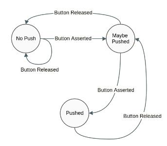
debounce():
Debounces increment hour and increment minute buttons through the use of a state machine ever 30 milliseconds. Uses the following state machine:
initialize():
Initializes microcontroller ports as inputs and outputs. PORT A is used solely for input from the pushbuttons and proximity sensors. PORT B is used as output for the control signals (alarm tone and motor control). PORTC is used as an output to choose which digit to display in the seven segment display as well as driving the colon and alarm clock led on the seven segment display. PORTD is used solely for output to drive the segments for the seven segment display.
main():
Calls initialization functions and creates a TRT task to update the seven segment display. It also polls the inputs.
Seven Segment Display Driver
The third major software-based component is continuously driving the seven-segment LED display. This device has four digits, each with its own decimal point, a colon, and an extra indicator dot. It is multiplexed such that it can be controlled by “only” fourteen output pins from the microcontroller: eight to control individual digit segments and the decimal points, four to enable or disable each digit, one to control the colon, and one to control the extra dot. The downside of this multiplexing is that the digits can be active only one at a time (otherwise, they would all be showing the same number).
We wrote a driver for the seven-segment display with an API that we use in the main software. This driver is a modular component: it knows nothing about the alarm clock functionality and could be incorporated directly into a future project using the display for a different purpose. It runs as a TRT task, continuously enabling the first digit only, setting the segment-controlling outputs appropriately, allowing the digit to be visible for 100 ms, and then repeating this for digits two, three, and four. We had to do some experimentation in finding the optimal refresh rate that would eliminate flicker in the seven segment display. We used the upper dot on the display to indicate whether the alarm is on/off and flashed the colon every second.
Functional Listing for Alarm Clock Code (SevenSeg.c)
seven_seg_setDigits(char d3, char d2, char d1, char d0):
Used to set the digits to display on the four digit seven segment display
seven_seg_setColon(bool col):
Turns on the colon on the display if col=true and off if col=false
seven_toggleColon():
Toggles colon on display. If the colon is already displayed, it will be turned off and vice versa.
seven_seg_setUpperDot(bool ud):
Turns on the upper dot on the display if ud=true and off if ud=false
seven_seg_init():
Initializes the ports used by the microcontroller to drive the seven segment display.
seven_seg_run():
TRT task that updates the display using the values set by seven_seg_setDigits(char d3, char d2, char d1, char d0). In every iteration, updates each digit sequentially while waiting in between updates to prevent flicker and incorrect updating.
Results
Our design met all the functional requirements of a traditional alarm clock. (One possible exception: it has no provisions for displaying the time in 12-hour AM/PM format.) It keeps time to a high degree of accuracy. Comparing it with a real clock over five minutes, the two devices deviated by less than a second. This is a result of the highly stable crystal oscillators used to drive the hardware timers of the microcontroller.
In terms of sensing movements towards the snooze button and alarm on/off toggle, our design was able to respond quick enough such that the user could not feasibly interact with these inputs without moving. The alarm clock itself was able to move at a speed of 10 in/s which was sufficiently fast enough to avoid a sedentary user while remaining slow enough for an user to actually interact with it. The alarm tone was loud enough to be heard in adjacent tones, and in our tests, we were able to wake up to it. The display itself had no visible flicker and was bright enough to be seen in both low- and high-light settings.
The weakest aspect of our alarm clock’s performance was the battery life. Our design required that the two sensors and the LED seven-segment display were powered and running continuously. Also, the microcontroller itself draws much more power than would be required of a less full-featured but more specialized chip. Running off the 6xAA battery pack, the alarm clock exhibits degraded functionality after one full night. The sensors are not as responsive, motion is slower, and the alarm tone is quieter and lower in pitch. The time is still displayed brightly and accurately.
Conclusions
We did not break any of the rules outlined in the IEEE Code of Ethics. Throughout our design process, we made sure to make our prototype as safe as possible. In this report, we do not exaggerate the successes of our design and we also state the shortcomings of the design for future improvement. We also made sure to clarify parts of our design that we had questions about so that we could ensure safety and proper functionality. For example, we wanted to use the motor power supply for the microcontroller power supply but we wanted to confirm that what we were planning was correct in case of any mistakes as incorrectly doing this step could have major reprecussions.
Also throughout our design process, we made sure to thoroughly read the datasheets of the new components we were using to make sure we knew how they worked. Tested the components beforehand to make sure that they were not defective and working properly. Tried to make sure our product was safe by taping any open wire connections and making sure the device did not need a heat sink for cooling if needed. We also made sure to document all the outside sources we used in our project so as to identify our sources properly.
Safety and Accessibility
We deem our design to be safe for general use. It uses low voltages (under 9 V) for all components, is not heavy, has no sharp edges, and moves at a relatively low speed unlikely to cause injury to humans or house pets. The motors and gearboxes are protected by the chassis and are not readily accessible, reducing the risk of anything becoming entangled in the moving parts.
The moving alarm clock is easily usable by the general population. The seven-segment display is bright enough to be read in daylight or night, and the alarm tone should be loud enough to wake heavy sleepers but not too loud as to cause pain. However, the unit may not be useful to those with physical disabilities that prevent them from chasing after it. A possible future development could be to have the option of disabling motion, increasing its usefulness for such people. It can also give able-bodied individuals the option to “be lazy” and not be required to chase after it on a day when they can sleep in, for example.
Future Possibilities
There are a number of additional features we would have added if we had more time. The foremost amongst them is power management. The four digit seven segment display we use drew a lot of power and consequently our current design had a low battery life. One solution we could implement would be disabling the display and sleeping the microcontroller when the user does not need to see the display. One such time would be when the user is sleeping. The sensors would be used as interrupts which would wake up the microcontroller.
This way the user needs only to make a motion towards the alarm clock for the display to show again. This behavior should be triggered in a dark environment which usually indicates the user is sleeping. This would also make the user’s sleeping environment more peaceful by making the room darker. Another potential solution is adding a wireless charging capability for the alarm clock. This means while the alarm clock is at rest (not running), it should be placed on a dock which would charge the alarm clock wirelessly. This means that the alarm clock will be fully charged when it starts ringing.
Alarm Clock
While our alarm clock was very effective in running away, it could be inconvenient and frustrating for sleepier users to constantly run after the clock. One soultion would be to limit the number of times the clock can run away as the objective is to force the user to get out of bed to turn the alarm clock off. Once the clock has moved a few times, the clock will be far enough from most users that additional movement would be redundant. This could also be an option for the user. We could also add obstacle detection for the alarm clock to prevent it from crashing and not being able to move as far.
Intellectual Property Considerations
We used Bruce Land’s adaptation of Tiny Real Time (TRT), a real-time kernel originally written by Dan Henriksson and Anton Cervin in our project. We used CircuitDB‘s square wave oscillator design to implement ours. More details on the original sources can be found in the References section at the end of this document. We also used the motor control circuit presented in Lab 4. Other than that, all of the software and hardware design was original.
Appendices
We had a budget of $100 for this project. The following table shows a list of parts used and their associated costs. (Not included: resistors, capacitors, wires.)
| Item | Vendor | Unit Price | Quantity | Cost |
| ATMega 1284p microcontroller | ECE 4760 lab | $5.00 | 1 | $5.00 |
| 7-segment display, 4 digit | Sparkfun | $1.95 | 1 | $1.95 |
| Breadboard | ECE 4760 lab | $6.00 | 2 | $12.00 |
| 1.5W 8 Ohm Speaker | Mouser | $4.03 | 1 | $4.03 |
| Pololu Carrier with Sharp GP2Y0D810Z0F Digital Distance Sensor 10cm | Pololu | $6.95 | 2 | $13.90 |
| 555 Timer IC | ECE 4760 lab | $0.00 | 1 | $0.00 |
| BUZ73 Transistor | ECE 4760 lab | $0.00 | 1 | $0.00 |
| 4N35 Optoisolator | ECE 4760 lab | $0.00 | 1 | $0.00 |
| 1N4001 Diode | ECE 4760 lab | $0.00 | 2 | $0.00 |
| AA Batteries (Sony 8-pack) | The Cornell Store | $1.161/2 ea. | 6 | $4.66 |
| Dagu Rover 5 Tracked Chassis | Pololu | $49.95 | 1 | $49.95 |
| Total Cost | $91.49 |
Source Code
AlarmClock.cThe seven-segment display driver:
SevenSeg.c
SevenSeg.h
Specific Tasks
For the most part, we took a layered collaboration approach to this project. Both of us worked together on the majority of the tasks. As a result it’s hard to divide the project into individual tasks that each member did. For the most part, Drew was more invovled with the software design while Imad was more involved with the hardware design.
Source: A Moving Alarm Clock
-
How does the alarm clock respond when the user tries to silence it?
The clock moves away from the user when a proximity sensor detects a finger near the snooze button. -
What format does the alarm clock use to display the time?
The device displays the time in a 24-hour format on a seven-segment LED display. -
How is the alarm tone generated in this design?
The alarm tone is generated using a hardware oscillator implemented with a 555 timer IC tuned to roughly 1000 Hz. -
Can the user set a snooze duration?
Yes, pressing the snooze button resets the alarm for 9 minutes into the future. -
What type of chassis and wheels are used for movement?
The unit is mounted on a Dagu Rover 5 tracked chassis with caterpillar-style wheels driven by two small DC motors. -
How long does the battery last during operation?
The design exhibits degraded functionality after one full night due to high power consumption by the sensors and display. -
What safety measures were taken regarding voltage and moving parts?
The device uses low voltages under 9V, has no sharp edges, and protects motors within the chassis to prevent entanglement.