Summary of A Pretty Good Wattmeter For Bench Use using microcontroller
This article describes a low-cost, 15-watt AC true power wattmeter using a two-quadrant multiplier. Optimized for 120 VAC, it measures power by floating a digital voltmeter on the AC neutral. The circuit is housed in an outlet box with safety banana plugs and can be modified for different ranges by changing the shunt resistor. It requires moderate analog circuit skills to build but offers high resolution for measuring line-powered switching circuits.
Parts used in the AC True Power Wattmeter:
- Two quadrant multiplier
- Shunt resistor
- Digital voltmeter (DVM)
- Outlet box
- Safety banana plugs
- AC receptacle
- Captive leads
Briefly,
• AC True Watts using two quadrant multiplier
• Optimized for 120 VAC (can be changed)
• 15 watt full scale (can be changed)
• Uses DVM floating on AC Neutral as display
• Requires moderately high level of analog circuit skill
• Very inexpensive
Find updates at: www.projects.cappels.org
Introduction
I am doing some work with AC line powered switching circuits and needed a way to measure the true power consumed by the circuit. This little circuit, which seems to have first surfaced in a circuit by Carl Nelson in National Semiconductor application note #222 in 1979, and has been updated by twice in print and once in video Robert Pease at National Semiconductor.
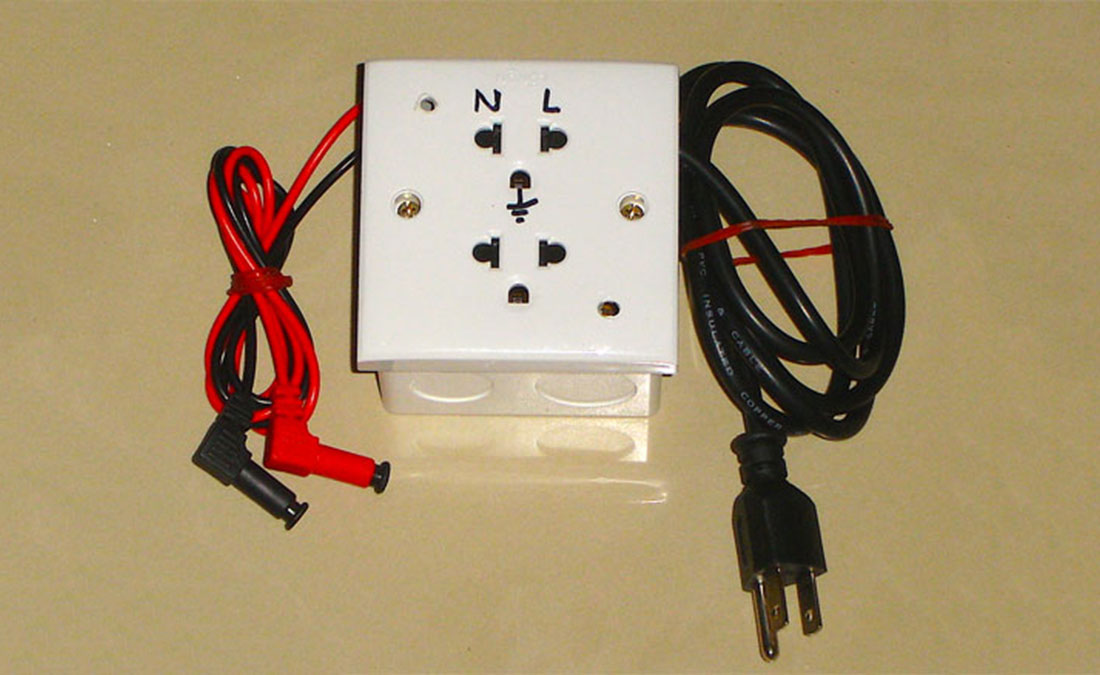
In my implementation, the wattmeter circuitry is contained in an outlet box
and captive leads allow AC voltage input and connection to a digital voltmeter.
The load is plugged into the AC receptacle on the box, leaving an additional
outlet for the voltmeter or a second load. Notice that the banana plugs are the
“safety” types with sheathed contacts so that there is little exposed metal.
The circuit it self is a simple two quadrant multiplier and as such, it only calculates the load power based on one half of the power cycle. This is not a problem for most loads, which draw the same current wave form on both half cycles. For the rare case in which the load draws different current wave forms in the two halves of the power line cycle (assuming single phase power lines) one merely needs to read the power, reverse the plug, read the power, and then average the two readings. I built one, a single range device that measures up to 15 watts with a resolution of 10 milliwatts, using a DVM with 100 microvolt resolution on its 200 millivolt scale. Actually, it can read 20 watts with a slight of linearity. The meter can be modified for other ranges by changing the shunt resistor. A multirange version is described in the references.
REFERENCES
To start with, National Semiconductor Note #222, July 1979
Super Matched Bipolar Transistor Pair Sets New Standards for Drift and Noise
www.national.com/an/AN/AN-222.pdf
Robert Pease’s prelude, how to make a shunt for the wattmeter, What’s All This Shunt Stuff, Anyhow?
http://electronicdesign.com/article/articles/what-s-all-this-shunt-stuff-anyhow-2144.aspx
The Robert Pease article with some circuit improvements, What’s All This Wattmeter Stuff, Anyhow?
http://electronicdesign.com/article/test-and-measurement/what-s-all-this-wattmeter-stuff-anyhow-2190.aspx
Another Robert Pease article, this one making it multi-range, RAP’s Multirange Wattmeter
http://electronicdesign.com/article/test-and-measurement/rap-s-multirange-wattmeter2191.aspx
Youtube video in which Bob Pease explains the circuit and discusses improvements
http://www.youtube.com/watch?v=mkLCs0dBX8E
Same video, different URL
http://video.google.com/videoplay?docid=-8509961694948158452#
Gary Lecomte “Chemelec” in British Colombia, implementation of the wattmeter
including a printed circuit design and a different version of the shunt resistor.
http://www3.telus.net/chemelec/Projects/Watt-Meter/Watt-Meter.htm
- How does the wattmeter measure true power?
The circuit uses a two quadrant multiplier to calculate load power based on one half of the power cycle. - Can this device measure loads with different current waveforms?
Yes, by reading the power, reversing the plug, reading again, and averaging the two readings. - What is the full scale measurement range of the described device?
The single range device built measures up to 15 watts with a resolution of 10 milliwatts. - How can the measurement range be changed?
The meter can be modified for other ranges by changing the shunt resistor. - What type of display is required for this project?
The circuit requires a DVM floating on AC Neutral as the display. - Is this project suitable for beginners?
No, it requires a moderately high level of analog circuit skill. - What voltage is the circuit optimized for?
The design is optimized for 120 VAC, though this can be changed.