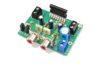
Today we present you a stereo 10 + 10 Watts audio amplifier based on TDA7297SA, a monolithic dual bridge amplifier that is suitable to be used in projects that feature access to a single 12 volts power supply.
This is a compact stereo amplifier: its field of application range from car stereo to portable audiovisual equipments (eg: for sport or public events, conferences or even emergency protection and safety mission equipements such as those needed after distaster events)
The heart of the amplifier is the TDA7297SA integrated from STMicroelectronics, a monolithic dual bridge amplifier capable of delivering, in fact, 10 + 10 watts.
The solution based on the bridge amplifier allows us to overcome the limitation in terms of maximum output power that you can get from a conventional amplifier powered with 12 volts, which is about 2.25 Watt. This solution gives you four times more power.
TDA7297SA contains two separate amplifiers in a bridge configuration in order to allow the realization of a stereo system within a single integrated element. TDA7297SA does not require external components for the bootstrap (the ignition and control sequence of power supply and amplification stages, used to avoid the formation of transients that end up in “bumps” on the speakers).
Two pins are availabe to externally manage Stand-by and muting: this allows you to control the power amplifier with a microcontroller, (as it’s the case when used in car audio) or, such as in the case of the project we present, can be used to make it manageable by a few discrete components that introduce required delays and voltage levels.
The power supply circuit is typically done by connecting to a car battery or to a 12 volts power supply stabilized in continuous current. The positive goest to pins 3 and 13 (VCC) while the negative goes to pin 8 (GNDP – Power ground) and 9 (GNDS- Mass of the audio signal.)
The left and right stereo inputs are respectively connected to pins 4 and 12 with C6 and C7 filter capacitors in the middle (to erase the DC component of the signal). Outputs are directed to the speakers from pins 1 and 2 for the right channel and 14 and 15 for the left channel.
As mentioned above we provided a circuit for the “manual” management of STANDBY and MUTE inputs to free ourselves from using a microcontroller and make the scheme as flexible as possible.
The start up procedure of amplification requires power-up and then to bring in high tension, respectively, in sequence, the STANDBY and MUTE inputs.
For more detail: A versatile, powerful 10 + 10 W Audio amplifier

