Summary of ACTIVE ELECTRONIC LOAD CIRCUIT ATMEGA88 100W DUMMY LOAD
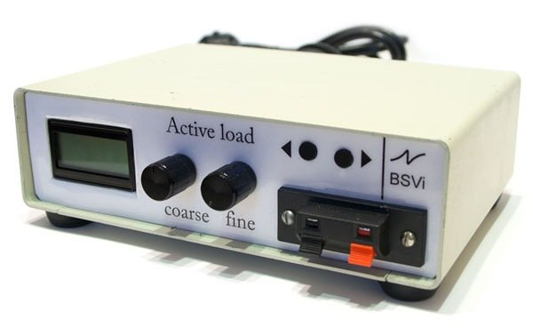
This article details the construction of a custom 100W active electronic load capable of handling up to 200V and 5A. The project features adjustable current consumption, periodic on/off modes for feedback testing, and includes an LED indicator with a cooling fan. Built using an old LPT port case and an AVR microcontroller, the device uses a simple circuit design with specific components like the BYV32E-200 diode and custom cutting techniques for the steel housing.
Parts used in the Active Electronic Load:
- Old switch LPT port case
- LED indicator
- M2.5 screws
- Dremel tool
- Self-made cutting discs from grinders
- Power transistor
- Computer fan
- Resistors (R5, R18, R20, R21)
- Microcontroller (AVR/ATmega88)
- Op-amp (U6)
- Diode (BYV32E-200)
In each electronic device in one form or another there is a power supply unit (PSU). Of course, because no one will work for free. Before connecting to the circuit, it would be nice to see how the PSU works at different loads.
Personally, I am not inspired by the search for a set of different-sized resistances with subsequent testing of the power supply with each of them; it is much more convenient to make a “load” that can be smoothly adjusted.
What did you want
So what did I want to get as a result?
-
Current consumption 0-5A (enough almost everywhere)
-
Power consumption – up to 100W (enough for almost any power supply)
-
Maximum voltage – 200V
-
Current indication
-
Mode when the load is periodically turned on and off ( for testing and setting feedback )
Housing
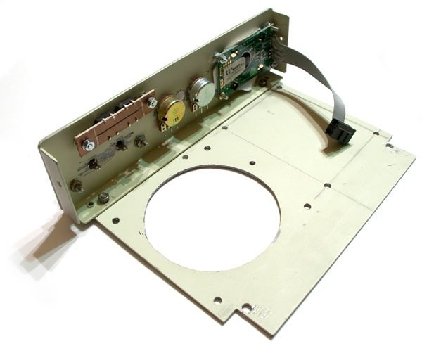
The body (like almost all the other parts), I pulled out of the old stock. Yes, I bought only an indicator and M2.5 screws for it, the rest I already had.
The case from some old switch LPT ports of ancient times, the giblets were pulled out and put to the trash can.
Cutting out the holes for the indicator and for the fan was absolutely epic, because the body is made of mercilessly thick steel.
Stalyuk I cut Dremel, and here’s what I can say:
-
Self-made cutting discs for Dremel from grinders are absolutely steering.
-
It is necessary to cut thick metal with a disk standing at 45 degrees to the metal plane, then the cut is smooth.
I cut such a huge hole, and not just drilled a dozen small holes because the power transistor did not have enough body height.
The photo shows how it happened. Taking into account the fact that this is a handwork, it turned out pretty well.
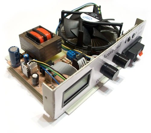
Electronics
Active load electronics are as simple as boots. You can see the scheme here:
There is nothing fundamentally new there for you.
Highlights:
-
What surprised me is that there are very specific datasheets for computer fans. In the diagram, the FanPower leg turns on the fan. At the same time it starts spinning at minimum speed. Theoretically, it is possible to start PWM on the FanSpeed foot and control the fan smoothly. But I just turn it on or off.Three stages will turn out: Off, low speed, high speed.
-
Current adjustment is assembled as a divider on resistors R5, R18 and resistors R20 and R21 (in gray square.)
-
The current switch is quite exotic (it was stuck when the board was ready) – when the DisableCurrent leg is in the input mode on the microcontroller, the U6 U op-amp normally controls the current of the power transistor. When the controller wants to turn off the current, it puts this foot in a high state. OU ofigevat from, as it seems to him, a huge current through the power transistor, and quickly closes it.
-
As a protective (reversal) diode, I found the BYV32E-200. Quite an interesting diode – physically it is a normal pn diode, but its fall is more like a Schottky diode.
Soft
Software is my attempt to lose with C ++ on microcontrollers. On the one hand, it turned out to be interesting, on the other hand, there are a lot of places in the pros where they just make me furious.Firmware for AVR under IAR. It turned out, as always when trying to play, crooked.
In any case, the advantages for microcontrollers are the topic of a separate article.
Files
Download all the documentation here (there is also a hex):
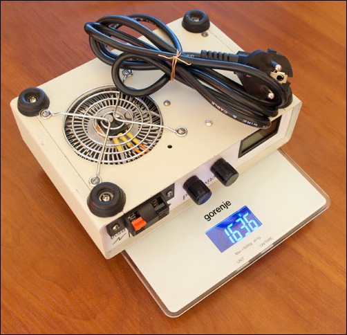
What happened
This work weighs quite well, and causes a sensation of a well-made device. One hundred watts dissipates, though with decent heating (And no one said it would be easy).
Some of the parameters did not turn out the way they wanted, but they’re too lazy to redo them, moreover, they are not too critical for me. For example, the turn-on time is 80µS. This is not exactly a delta pulse, and the feedback cannot show the transition process in all its glory. On the other hand, frankly I get on in OS it will help to reveal.
Vidushnik with a demonstration
Yes, yes, I myself know that the quality is terrible and it is time to buy a new camera. I am now in her active selection. I don’t know what to do with my congenital inhibition, but I hope I’ll fix it))
Protel pcb project’s source code and have the schema files, IAR.
Source: http://bsvi.ru/aktivnaya-nagruzka/alternative active-electronic-load-circuit-atmega88-100w-dummy-load.rar
- What is the maximum power consumption of this device?
The device can handle power consumption up to 100W. - How can I adjust the current consumption?
Current adjustment is assembled as a divider on resistors R5, R18, R20, and R21. - Does the fan support smooth speed control?
Theoretically PWM control is possible, but the author only implemented three stages: Off, low speed, and high speed. - What happens when the DisableCurrent leg is set to a high state?
The op-amp quickly closes the power transistor to prevent huge current flow. - Which diode was used as a protective reversal component?
The author found and used the BYV32E-200 diode. - Can this load be used to test power supply feedback?
Yes, it has a mode where the load is periodically turned on and off for testing and setting feedback. - What material was used to cut the holes in the housing?
Self-made cutting discs from grinders were used with a Dremel to cut the thick steel body. - Is the turn-on time of the device suitable for delta pulses?
No, the turn-on time is 80µS, which is not exactly a delta pulse.