
Summary of USING NXP’S NXQ1TXH5 QI CHARGING CIRCUIT
NXP’s NXQ1TXH5 is a Qi-compatible wireless power transmitter IC in a 5 mm × 5 mm, 32-pin HVQFN package. It simplifies creating a Qi charger with a basic circuit but poses prototyping challenges and coil selection issues. The chip adds advanced features: per-client power monitoring and restriction, LED and buzzer outputs, an I2C interface, and a low-power pinging detection mode to reduce standby consumption. Power derating reduces efficiency at low transfer levels. The public datasheet is limited; developers should contact NXP for detailed documentation.
Parts used in the NXQ1TXH5 Qi charging project:
- NXP NXQ1TXH5 Qi transmitter IC (5 mm × 5 mm, 32-pin HVQFN)
- Qi-compatible transmit coil (appropriate for IC)
- Decoupling capacitors (multiple)
- LED for status indication
- Buzzer for audible feedback
- USB wallwart power supply
- PCB for mounting IC and components
- Soldering/reflow process or prototyping adapter for HVQFN package
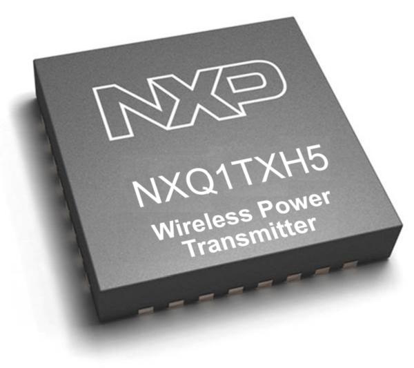
Adding wireless charging to furniture and other consumer goods is a nice way to add some oomph to an otherwise boring product. NXP’s NXQ1TXH5 provides an interesting, albeit difficult-to-prototype way around the problem.
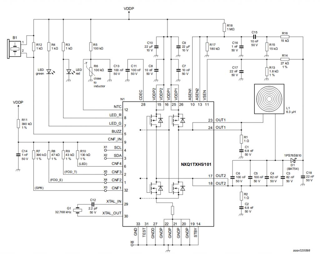
Creating a Qi-compatible is as easy as assembling the example circuit shown in figure one. From a technical point of view, the diagram is full of decoupling capacitors but does not require much in terms of complexity. The main issues are a) finding a correct coil and b) prototyping the device – NXP uses a 5 mm x 5 mm, 32-pin HVQFN package which is not really suited to non-reflow soldering processes.
Advanced functionality
While most charging ICs limit themselves to simply providing the oscillating field needed for transferring power, NXP adds a few extremely nifty features to its chip. First of all, the NXQ1TXH5 is able to monitor and restrict the amount of power supplied to its clients. This way, multiple chips can power themselves from a single USB wallwart. Sadly, this process does not have unlimited efficiency – look at figure two to see a power derating curve.
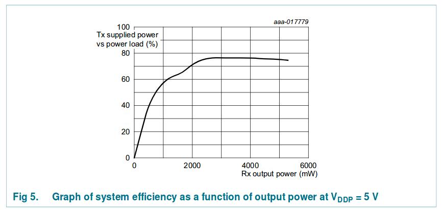
…QI’s already-bad efficiency becomes terrible if but small amounts of power are to be transferred
User convenience is enhanced by the presence of LED and buzzer outputs: emitting a satisfying beep as charging starts makes handling the charger so much more pleasant. Finally, the part also has an I2C interface, which is not documented.
Power consumption is reduced via a dedicated pinging circuit. When no device is present, NXPs chip hibernates the main Qi charging system and emits special waveforms to detect hardware – this way, standby can be accomplished with minimal power consumption.
Sadly, the public datasheet of the part is short and tardy – developers who want to use the chip in anger should ask their local NXP office for further information and/or a more detailed set of documents.
Source: USING NXP’S NXQ1TXH5 QI CHARGING CIRCUIT
- How difficult is it to prototype the NXQ1TXH5?
Prototyping is difficult because the IC is in a 5 mm × 5 mm, 32-pin HVQFN package not suited to non-reflow soldering processes. - Can a single USB wallwart power multiple NXQ1TXH5 chips?
Yes, the chip can monitor and restrict power supplied to clients so multiple chips can power themselves from a single USB wallwart, though with efficiency limitations. - What features beyond power transfer does the NXQ1TXH5 provide?
It provides per-client power monitoring and restriction, LED and buzzer outputs, an I2C interface, and a dedicated pinging detection mode for low standby power. - Does the NXQ1TXH5 reduce power consumption when no device is present?
Yes, it hibernates the main Qi charging system and emits special waveforms to detect hardware, enabling minimal standby power consumption. - What is the main technical challenge when using this IC?
The main challenges are finding a correct coil and prototyping the HVQFN package. - How does the NXQ1TXH5 perform at low power transfer levels?
Performance degrades: power derating causes Qi efficiency to become much worse at small transfer amounts. - Is the I2C interface documented in the public datasheet?
No, the I2C interface is mentioned but not documented in the public datasheet. - Where should developers seek more detailed information?
Developers should contact their local NXP office for further information and a more detailed set of documents.
