The ESP8266-01 only has a limited number of I/O pins (only 4). Fortunately these pins can be used for I2C communication, allowing us to add a hoist of other chips.
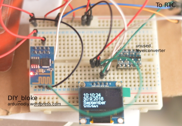
I wanted to add an RTC to the ESP8266-01 and for testing purposes I did not want to always have to go to an ESP8266 generated webpage to check the output and I found keeping it attached to the USB port too cumbersome, so I needed to add some sort of output device.

Ofcourse there is the LCD and people have been adding that to the ESP8266, but it is 5 Volt. Though apparently the voltage on the I2C pins of the LCD falls within the tolerance of the ESP8266, I did not want to risk that, so I would need a voltage leveler, which I found too cumbersome just for testing purposes. Therefore I decided to use a simple and relatively cheap OLED display. These are I2C by nature and work on 3.3 Volt.
Anyway, for this project the shopping list is as follows:
BOM:
- ESP8266-01
- DS3231 or DS1307 RTC
- OLED 128×64
- 3.3 Volt PSU
- breadboard
- 2×4 female headers
- 2×4 male headers
- piece of veroboard 4×4 holes
- various colors of breadboard wires
- A 3v3 USB to TTL converter
- Adafruit RTCLib library
- SSD1306 OLED library
With regard to the OLED library, Adafruit also provides one, but it requires instalation of the GFX library as well, so I opted for another library. Also I understood some people having trouble with it that needed changes in the *.h file.
It is said to work though on the ESP8266.
Just some remarks on the BOM:
- If you still need to buy an ESP8266-01, consider buying a newer one. The 01 version is not particularly cheaper than say the 12 version and for a few euro more you even have a micro USB connection integrated on it as e.g. in the NodeMCU
- When I mention the DS3231 or DS1307, I mean a fully integrated module that has likely also an EEPROM on board. Pricewise it is foolish to buy a separate DS3231/DS1307 chip and a x-tal and battery holder. When buying a module, watch out as the come with or without battery and the price difference might be minimal.
I would advise getting the DS3231 as that is more accurate than the DS1307. The DS1307 has some on chip NonVolatileRam though that may come in handy if you have to do a lot of writes to memory, which would eventually kill an EEPROM - The female and male headers and the piece of veroboard I used to make a breadboard friendly converter for the ESP8266-01 pin header. You may have your own solution for it. However, discussing the adapter in depth is not my goal here, basically it turns the 2 row header base into a 4 row header base that fits around the separator in the breadboard
- Make sure you use a 3.3Volt USB to TTL converter. There are some switchable ones. Check if the switch is set to 3.3Volt. A very handy programming device for the ESP8266-01 is this one. Especially if you plan to program a lot of chips.
- There are different color OLEDs, mostly blue ones and white ones (I refer to the text color) there are some however that have to top half a different color (often yellow) than the bottom half. If you see that your OLED is not broken, it was designed for a special application, like a cellphone
Step 1: The Connections

This couldn’t be simpler:
I used GPIO0 as SDA and GPIO2 as SCL.
The RTC and OLED have the pin nominations clearly stamped on them so you only need to connect as follows
All Vcc-s together
All Grounds together
RTC and OLED SDA pins to GPIO0
RTC and OLED SCL pins to GPIO2
Finally connect the CH_PD pin with Vcc
Make sure you identify the proper pins. Your modules may have a pin sequence that differs from mine.
I did not add any pull-up resistors as my RTC has those and as far as I could see my OLED has too.
If your modules do not, you need 2 pull up resistors on the SDA and SCL lines 2k2 to 4k7 is a good value.
If you plan to add more modules that may have an internal pull up already… chose 4k7
Step 2: The Code
I presume you do know how to program the ESP8266. In short:
Connect Tx<->Rx (meaning the Tx of your ESP to the Rx of your USB-TTL converter)
Connect Rx<->Tx
CH_PD<->Vcc
Connect GPIO0 <->Grnd
/* ************************************
 Read the time from RTC and display on OLED
 with an ESP8266<br> sda=0, scl=2
* *************************************/

// Libraries
#include <Wire.h>
#include "SSD1306.h" // alias for `#include "SSD1306Wire.h"`
#include "RTClib.h" //  Lady Ada
//Object declarations
RTC_DS1307 rtc;            // RTC
SSD1306  display(0x3c, 0, 2);//0x3C being the usual address of the OLED

//Month and Day Arrays. Put in Language of your choice, omitt the 'day' part of the weekdays
char *maand[] =
{
  "Januari", "Februari", "Maart", "April", "Mei", "Juni", "Juli", "Augustus", "September", "Oktober", "November", "December"
};
char *dagen[] = {"Zon", "Maan", "Dins", "Woens", "Donder", "Vrij", "Zater" };


// date and time variables
byte m = 0;          // contains the minutes, refreshed each loop
byte h = 0;          // contains the hours, refreshed each loop
byte s = 0;         // contains the seconds, refreshed each loop
byte mo = 0;       // contains the month, refreshes each loop
int j = 0;           // contains the year, refreshed each loop
byte d = 0;         // contains the day (1-31)
byte dag = 0;     // contains day of week (0-6)

void setup() {
  Wire.pins(0, 2);// yes, see text
  Wire.begin(0,2);// 0=sda, 2=scl
  rtc.begin();

// reading of time here only necessary if you want to use it in setup
  DateTime now = rtc.now();
  dag = now.dayOfTheWeek();
  j = now.year();
  mo = now.month();
  d = now.day();
  h = now.hour();
  m = now.minute();
  s = now.second();
  DateTime compiled = DateTime(__DATE__, __TIME__);
  if (now.unixtime() < compiled.unixtime())
  {
    Serial.print(F("Current Unix time"));
    Serial.println(now.unixtime());
    Serial.print(F("Compiled Unix time"));
    Serial.println(compiled.unixtime());
    Serial.println("RTC is older than compile time! Updating");
    // following line sets the RTC to the date & time this sketch was compiled<br>   // uncomment to set the time
    // rtc.adjust(DateTime(F(__DATE__), F(__TIME__)));
  }

  // Initialise the display.
  display.init();
  display.flipScreenVertically();// flipping came in handy for me with regard
                                                                // to screen position
  display.setFont(ArialMT_Plain_10);

}


void loop() {
  display.clear();
  DateTime now = rtc.now();
  dag = now.dayOfTheWeek();
  j = now.year();
  mo = now.month();
  d = now.day();
  h = now.hour();
  m = now.minute();
  s = now.second();

  display.setTextAlignment(TEXT_ALIGN_LEFT);
  display.setFont(ArialMT_Plain_16);
  String t = String(h) + ":" + String(m) + ":" + String(s);
  String t2 = String(d) + ":"  + String(mo) + ":" + String(j);
  display.drawString(0, 10, t);//
  display.drawString(0, 24, t2);
  display.drawString(0, 38, maand[mo - 1]);
  String d = dagen[dag];
  d = d + "dag";//adding the word 'dag' (=day)  to the names of the days
  display.drawString(0, 52, d);
  // write the buffer to the display
  display.display();
  delay(10);
}
The code is fairly straightforward but it does contain some peculiarities.
I make a call to ‘Wire.pins(sda,scl)’. That seems redundant and in fact the call was deprecated, but apparently if any other library would make a call to ‘Wire()’ the proper definition of the pins for the sda and scl can get lost. So I left them both in for safety.
If you still have an old RTCLib you may get an error on ‘dayOfTheWeek’. That is because it used to be called ‘dayOfWeek’ but it got changed: update your library.
The last line, with the day on it, may be just a bit too much size for your OLED: set the font smaller (say ‘Plain_10’) and alter the print positions (the second digits in the display.drawString(0, x, string); statements)
Source: Adding an RTC and OLED to ESP8266-01