
Summary of Alarm clock DPR
This article details the design of a digital alarm clock using an ATmega32 microcontroller. It utilizes a 16-bit timer for timekeeping and features a 16x2 LCD for display. The system includes input buttons to set hours and minutes, with logic to trigger a buzzer when the alarm time is reached. Software tools like Atmel Studio 6.1 are used for programming, while hardware components such as crystals, capacitors, resistors, and transistors facilitate circuit operation.
Parts used in Digital Alarm Clock:
- ATmega32 microcontroller
- 11.0592MHz crystal
- Two 22pF capacitors
- 5V power supply
- JHD_162ALCD (16x2 LCD)
- 100uF capacitor
- Four buttons
- Six 10KΩ resistors
- Four 100nF capacitors
- Two three-pin switches
- 2N2222 transistor
- Buzzer
- 200Ω resistor
- AVR-ISP PROGRAMMER
In this project, we will create a straightforward alarm clock using the timers of the ATmega32 microcontroller. The ATmega32A microcontroller features a 16-bit timer, which will be utilized for tracking seconds and constructing a digital clock.
Hardware components include the ATmega32 microcontroller, an 11.0592MHz crystal, two 22pF capacitors, a 5V power supply, AVR-ISP PROGRAMMER, a JHD_162ALCD (16×2 LCD), a 100uF capacitor connected to the power supply, four buttons, six 10KΩ resistors, four 100nF capacitors, two three-pin switches, a 2N2222 transistor, a buzzer, and a 200Ω resistor.
Software tools encompass Atmel Studio 6.1, ProgISP, or Flash Magic.
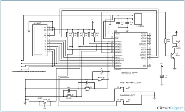
Here are the connections for the LCD:
1. Connect PIN1 (VSS) to ground.
2. Connect PIN2 (VDD or VCC) to +5v power.
3. Connect PIN3 (VEE) to ground (provides maximum contrast, ideal for beginners).
4. Connect PIN4 (RS or Register Selection) to PD6 of the microcontroller (uC).
5. Connect PIN5 (RW or Read/Write) to ground (sets the LCD in read mode, simplifying communication for the user).
6. Connect PIN6 (E or Enable) to PD5 of the microcontroller (uC).
7. Connect PIN7 (D0) to PB0 of the microcontroller (uC).
8. Connect PIN8 (D1) to PB1 of the microcontroller (uC).
9. Connect PIN9 (D2) to PB2 of the microcontroller (uC).
10. Connect PIN10 (D3) to PB3 of the microcontroller (uC).
11. Connect PIN11 (D4) to PB4 of the microcontroller (uC).
12. Connect PIN12 (D5) to PB5 of the microcontroller (uC).
13. Connect PIN13 (D6) to PB6 of the microcontroller (uC).
14. Connect PIN14 (D7) to PB7 of the microcontroller (uC).
The functioning of the alarm clock is detailed step by step in the following code: [Code description follows].
Code:
/* —- Code for Digital Clock with Alarm using AVR Microcontroller —— */
#include <avr/io.h>
#define F_CPU 11059200
#include <util/delay.h>
#include <stdlib.h>
#include <avr/interrupt.h>
#define enable 5
#define registerselection 6
void send_a_command(unsigned char command);
void send_a_character(unsigned char character);
void send_a_string(char *string_of_characters);
ISR(TIMER1_COMPA_vect);
static volatile int SEC =0;
static volatile int MIN =0;
static volatile int HOU =0;
int main(void)
{
DDRA = 0b11000000;
DDRB = 0xFF;
DDRD = 0xFF;
TCCR1B |=(1<<CS12)|(1<<CS10)|(1<<WGM12);
OCR1A=10800;
sei();
TIMSK |=(1<<OCIE1A);
char SHOWSEC [2];
char SHOWMIN [2];
char SHOWHOU [2];
int ALSEC = 0;
int ALMIN = 0;
int ALHOU = 0;
char SHOWALSEC [2];
char SHOWALMIN [2];
char SHOWALHOU [2];
send_a_command(0x01); //Clear Screen 0x01 = 00000001
_delay_ms(50);
send_a_command(0x38);
_delay_ms(50);
send_a_command(0b00001111);
_delay_ms(50);
while(1)
{
itoa(HOU/10,SHOWHOU,10);
send_a_string(SHOWHOU);
itoa(HOU%10,SHOWHOU,10);
send_a_string(SHOWHOU);
send_a_string (“:”);
send_a_command(0x80 + 3);
itoa(MIN/10,SHOWMIN,10);
send_a_string(SHOWMIN);
itoa(MIN%10,SHOWMIN,10);
send_a_string(SHOWMIN);
send_a_command(0x80 + 5);
send_a_string (“:”);
send_a_command(0x80 + 6);
itoa(SEC/10,SHOWSEC,10);
send_a_string(SHOWSEC);
itoa(SEC%10,SHOWSEC,10);
send_a_string(SHOWSEC);
if (bit_is_set(PINA,5))
{
send_a_string(” ALM:ON “);
if ((ALHOU==HOU)&(ALMIN==MIN)&(ALSEC==SEC))
{
PORTA|=(1<<PINB7);
}
}
if (bit_is_clear(PINA,5))
{
send_a_string(” ALM:OFF”);
PORTA&=~(1<<PINB7);
}
send_a_command(0x80 + 0x40 + 0);
send_a_string (“ALARM:”);
send_a_command(0x80 + 0x40 + 7);
itoa(ALHOU/10,SHOWALHOU,10);
send_a_string(SHOWALHOU);
itoa(ALHOU%10,SHOWALHOU,10);
send_a_string(SHOWALHOU);
send_a_command(0x80 + 0x40 +9);
send_a_string (“:”);
send_a_command(0x80 + 0x40 +10);
itoa(ALMIN/10,SHOWALMIN,10);
send_a_string(SHOWALMIN);
itoa(ALMIN%10,SHOWALMIN,10);
send_a_string(SHOWALMIN);
send_a_command(0x80 + 0x40+ 12);
send_a_string (“:”);
send_a_command(0x80 + 0x40+ 13);
itoa(ALSEC/10,SHOWALSEC,10);
send_a_string(SHOWALSEC);
itoa(ALSEC%10,SHOWALSEC,10);
send_a_string(SHOWALSEC);
send_a_command(0x80 + 0);
if (bit_is_set(PINA,4))
{
if (bit_is_clear(PINA,0))
{
if (MIN<60)
{
MIN++;
_delay_ms(220);
}
if (MIN==60)
{
if (HOU<24)
{
HOU++;
}
MIN=0;
_delay_ms(220);
}
}
if (bit_is_clear(PINA,1))
{
if (MIN>0)
{
MIN–;
_delay_ms(220);
}
}
if (bit_is_clear(PINA,2))
{
if (HOU<24)
{
HOU++;
}
_delay_ms(220);
if (HOU==24)
{
HOU=0;
}
}
if (bit_is_clear(PINA,3))
{
if (HOU>0)
{
HOU–;
_delay_ms(220);
}
}
}
if (bit_is_clear(PINA,4))
{
if (bit_is_clear(PINA,0))
{
if (ALMIN<60)
{
ALMIN++;
_delay_ms(220);
}
if (ALMIN==60)
{
if (ALHOU<24)
{
ALHOU++;
}
ALMIN=0;
_delay_ms(220);
}
}
if (bit_is_clear(PINA,1))
{
if (ALMIN>0)
{
ALMIN–;
_delay_ms(220);
}
}
if (bit_is_clear(PINA,2))
{
if (ALHOU<24)
{
ALHOU++;
}
_delay_ms(220);
if (ALHOU==24)
{
ALHOU=0;
}
}
if (bit_is_clear(PINA,3))
{
if (ALHOU>0)
{
ALHOU–;
_delay_ms(220);
}
}
}
}
}
ISR(TIMER1_COMPA_vect)
{
if (SEC<60)
{
SEC++;
}
if (SEC==60)
{
if (MIN<60)
{
MIN++;
}
SEC=0;
}
if (MIN==60)
{
if (HOU<24)
{
HOU++;
}
MIN=0;
}
if (HOU==24)
{
HOU=0;
}
}
void send_a_command(unsigned char command)
{
PORTB = command;
PORTD &= ~ (1<<registerselection);
PORTD |= 1<<enable;
_delay_ms(3);
PORTD &= ~1<<enable;
PORTB = 0xFF;
}
void send_a_character(unsigned char character)
{
PORTB = character;
PORTD |= 1<<registerselection;
PORTD |= 1<<enable;
_delay_ms(3);
PORTD &= ~1<<enable;
PORTB = 0xFF;
}
void send_a_string(char *string_of_characters)
{
while(*string_of_characters > 0)
{
send_a_character(*string_of_characters++);
}
}
Source: Alarm clock DPR
-
What microcontroller is used in this project?
The ATmega32A microcontroller is used, featuring a 16-bit timer. -
How is the time tracking implemented?
A 16-bit timer within the ATmega32A is utilized for tracking seconds and constructing the digital clock. -
Which software tools are required for programming?
Atmel Studio 6.1, ProgISP, or Flash Magic are the recommended software tools. -
How is the LCD connected to the microcontroller?
PIN4 connects to PD6, PIN6 to PD5, and data pins D0-D7 connect to PB0 through PB7 respectively. -
Can the alarm be turned on and off?
Yes, the code checks bit settings on PINA to display ALM:ON or ALM:OFF status. -
What triggers the buzzer sound?
The buzzer activates when the current hour, minute, and second match the set alarm values. -
How are the hours and minutes adjusted?
Buttons connected to specific pins allow incrementing or decrementing the hour and minute values.
