
Summary of Alexa (voice) Controlled RF Remote
The author created an Alexa-controlled RF ceiling fan system because commercial learning remotes do not exist. By using an Adafruit Feather HUZZAH ESP8266 board, the project emulates a WeMo device to control a standard RF remote via relays. The setup involves hardwiring the remote's buttons, soldering components into a project box, and uploading custom C++ code to bridge voice commands with physical relay triggers, effectively automating the fan without needing a separate remote.
Parts used in the Alexa Controlled RF Remote:
- Adafruit Feather HUZZAH with ESP8266 WiFi board
- Ribbon wire
- Kest KS2E-M-DC3 Relay 3V
- Project box
- Soldering equipment
- Standard RF ceiling fan remote
- Computer for coding
The Amazon Echo, I absolutely love it, I finally have the home of the future
But When I want to turn on a ceiling fan, or use any device that uses a RF (Radio Frequency) Remote
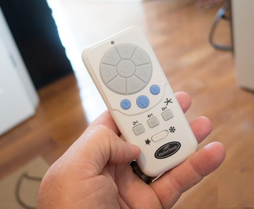
its back to the pile sitting on my coffee table in my living room.
I searched high and low for a learning remote for RF, but they do not exist.
so how does the saying go? The impossible just takes a little longer.
Step 1: Finding a Solution
There is a WONDERFUL company called ‘adafruit’
Adafruit website and Feather Demo
that makes wearable Arduino modules.
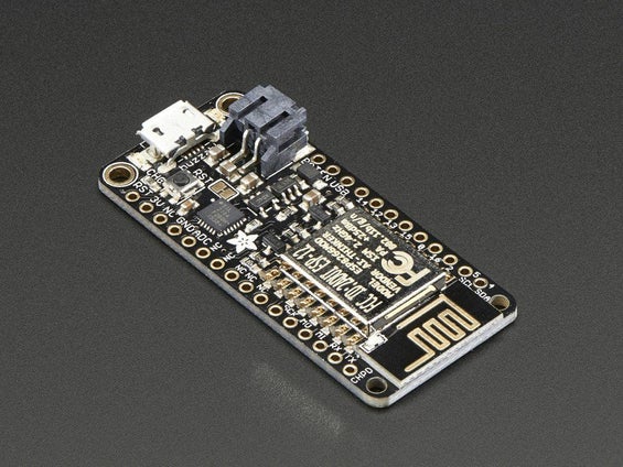
I found them originally when I was working on one of my costumes, well in that time they
have grown into a full fledged DIY paradise with boards, and parts, and gadgets and scripts to
do anything imaginable.
The part I used was a “Adafruit Feather HUZZAH with ESP8266 WiFi” board,
its a tiny 1″ x 3″ board that costs like $17.00
Code and tutorial based on the great open source lib & example code at http://tinkerman.cat/emulate-wemo-device-esp8266/… which is based off of the Python example code by http://tinkerman.cat/emulate-wemo-device-esp8266/…
Step 2: Hardware
Since RF remotes are still kinda proprietary, the only way I assumed i would be able to use one is
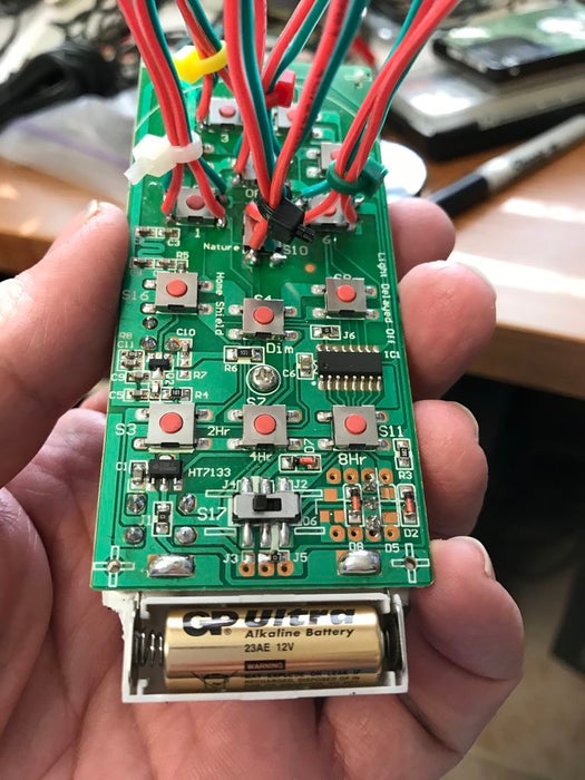
to “Assimilate” the remote, as part of my project, So I hardwired the select buttons on the remote
and would have a relay trigger them (as the button push)
I used ‘ribbon’ wire since I would be cramming this all into a project box, I needed wire that
has a bit of flexibility to it.
Step 3: The Software Monster
I haven’t coded in 5 years, maybe longer – but there where a lot of helpful guides and people on the Adafruit website.. they gave me tremendous guidance with the project.
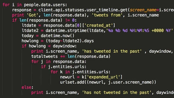
Here is my Code;
// Five DEVICES WORKING
#include #include #include “fauxmoESP.h”
#define WIFI_SSID “YOUR WIFI NAME” #define WIFI_PASS “YOURWIFIPW”
#define SERIAL_BAUDRATE 115200
fauxmoESP fauxmo;
#define FAN_PIN 12 // White wire — “1” // (LOW) – CLEAR #define TWO_PIN 13 // Black wire — OFF — RED #define MEDIUM_PIN 14 // Black — connector pin — YELLOW #define FAST_PIN 15 // Gray wire “6” — GREEN #define BREEZE_PIN 04 // Red wire (connector) //working BLACK
// PIN 16 UNUSABLE // PIN 0 UNUSABLE
volatile boolean fan_state = false; // off by default! volatile boolean fan_desired_state = false; // off by default!
volatile boolean medium_state = false; // off by default! volatile boolean medium_desired_state = false; // off by default!
volatile boolean fast_state = false; // off by default! volatile boolean fast_desired_state = false; // off by default!
volatile boolean Breeze_state = false; // off by default! volatile boolean Breeze_desired_state = false; // off by default! volatile boolean two_state = false; // off by default! volatile boolean two_desired_state = false; // off by default! // —————————————————————————– // Wifi // —————————————————————————–
void wifiSetup() { // Set WIFI module to STA mode WiFi.mode(WIFI_STA);
// Connect Serial.printf(“[WIFI] Connecting to %s “, WIFI_SSID); WiFi.begin(WIFI_SSID, WIFI_PASS);
// Wait while (WiFi.status() != WL_CONNECTED) { Serial.print(“.”); delay(100); } Serial.println();
// Connected! Serial.printf(“[WIFI] STATION Mode, SSID: %s, IP address: %s\n”, WiFi.SSID().c_str(), WiFi.localIP().toString().c_str()); }
void callback(uint8_t device_id, const char * device_name, bool state) { Serial.printf(“[ECHO] %s state: %s\n”, device_name, state ? “ON” : “OFF”); if ( (strcmp(device_name, “medium”) == 0) ) { // MEDIUM medium_desired_state = state; // Remember the new desired state }
if ( (strcmp(device_name, “fan”) == 0) ) { // FAN fan_desired_state = state; // Remember the new desired state }
if ( (strcmp(device_name, “fast”) == 0) ) { // FAST fast_desired_state = state; // Remember the new desired state } if ( (strcmp(device_name, “Breeze”) == 0) ) { // BREEZE Breeze_desired_state = state; // Remember the new desired state } } void setup() {
pinMode(FAN_PIN, OUTPUT); digitalWrite(FAN_PIN, LOW); pinMode(TWO_PIN, OUTPUT); digitalWrite(TWO_PIN, LOW); pinMode(MEDIUM_PIN, OUTPUT); digitalWrite(MEDIUM_PIN, LOW); pinMode(FAST_PIN, OUTPUT); digitalWrite(FAST_PIN, LOW); pinMode(BREEZE_PIN, OUTPUT); digitalWrite(BREEZE_PIN, LOW); // Init serial port and clean garbage Serial.begin(SERIAL_BAUDRATE); Serial.println(); Serial.println(); Serial.println(“Echo Control”); Serial.println(“After connection, ask Computer to ‘turn shit on and off”);
// Wifi wifiSetup();
// Fauxmo fauxmo.addDevice(“fan”); // works fauxmo.addDevice(“medium”); // works fauxmo.addDevice(“fast”); // works fauxmo.addDevice(“Breeze”); // works fauxmo.onMessage(callback); } void loop() { fauxmo.handle();
if (fan_state != fan_desired_state) { if (fan_desired_state) { // Transition to on Serial.println(“activating…”); digitalWrite(FAN_PIN, HIGH); delay(1000); // Safe to use delays here Serial.println(“…fan”); digitalWrite(FAN_PIN, LOW); } else { // Transition to off digitalWrite(TWO_PIN, HIGH); delay(1000); // Safe to use delays here Serial.println(“…turning off relay”); digitalWrite(TWO_PIN, LOW); } // We handled the state change, so the desired state becomes the current state fan_state = fan_desired_state; } { if (medium_state != medium_desired_state) { if (medium_desired_state) { // Transition to on Serial.println(“activating…”); digitalWrite(MEDIUM_PIN, HIGH); delay(1000); // Safe to use delays here Serial.println(“…Medium speed”); digitalWrite(MEDIUM_PIN, LOW); } else { // Transition to off digitalWrite(TWO_PIN, HIGH); delay(1000); // Safe to use delays here Serial.println(“…turning off relay”); digitalWrite(TWO_PIN, LOW); } // We handled the state change, so the desired state becomes the current state medium_state = medium_desired_state; }
}
if (fast_state != fast_desired_state) { if (fast_desired_state) { // Transition to on Serial.println(“Activating High speed…”); digitalWrite(FAST_PIN, HIGH); delay(1000); // Safe to use delays here Serial.println(“…Turning off Relay”); digitalWrite(FAST_PIN, LOW); } else { // Transition to off digitalWrite(TWO_PIN, HIGH); delay(1000); // Safe to use delays here Serial.println(“…turning off relay”); digitalWrite(TWO_PIN, LOW); }
// We handled the state change, so the desired state becomes the current state fast_state = fast_desired_state;
}
if (Breeze_state != Breeze_desired_state) { if (Breeze_desired_state) { // Transition to on Serial.println(“Activating Random Breeze…”); digitalWrite(BREEZE_PIN, HIGH); delay(1000); // Safe to use delays here Serial.println(“…Turning off Relay”); digitalWrite(BREEZE_PIN, LOW); } else { // Transition to off digitalWrite(TWO_PIN, HIGH); delay(1000); // Safe to use delays here Serial.println(“…turning off relay”); digitalWrite(TWO_PIN, LOW);
}
// We handled the state change, so the desired state becomes the current state Breeze_state = Breeze_desired_state;
} }
Step 4: The Hardware Monster
A lot of soldering both on the Adafruit and to the relays, The company sells relay boards, but they where SPST
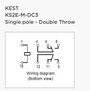
relays, and are kinda pricey, ($8 per) I went out onto the internet and bought a pile of relays, to see which ones
would work.. and found THESE: Kest KS2E-M-DC3 Relay 3V – about $2.00 a piece on All Electronic’s website
Then went about the fun of mounting them in a case, and wiring them all together.
Step 5: The Completed Project
This was about a week of coding and soldering, all for a small convenience, of not reaching for ANOTHER remote.
Source: Alexa (voice) Controlled RF Remote
- Why did the author start this project?
The author started the project because they could not find a learning remote that works with Radio Frequency (RF) devices like ceiling fans. - What specific microcontroller board was used for the solution?
The project utilizes an Adafruit Feather HUZZAH with ESP8266 WiFi board which costs around $17.00. - How does the hardware interface with the existing remote?
The author hardwired the select buttons on the original remote so that relays can trigger them as if a button were being pushed. - Which type of wire was chosen for the internal connections?
Ribbon wire was selected because it offers flexibility needed to cram all components into a small project box. - What software library is referenced in the code comments?
The code is based on the open source lib and example code found at tinkerman.cat/emulate-wemo-device-esp8266/. - How much did the individual relays cost compared to pre-made boards?
The author bought Kest KS2E-M-DC3 Relays for about $2.00 each instead of buying pricey pre-made relay boards at $8 per piece. - What are the five distinct fan speeds or modes controlled by the code?
The code controls five devices named fan, medium, fast, Breeze, and two. - What is the primary benefit of completing this DIY project?
The main convenience gained is the ability to control the fan via voice without having to reach for another physical remote.
