Introduction:
I built this project as a birthday present for my oldest daughter. She had recently moved far from home and I wanted her to know her family was still there for her. I chose a Lord of the Rings theme and aesthetic because she and I had watched the movies together as she was growing up. The screen in the box displays a personal message then a compass rose that indicates magnetic north along with an arrow pointing toward home. The distance to home is also shown.
Supplies:
Adafruit:
LSM303AGR Accelerometer Magnetometer, STEMMA QT
Assembled Adafruit HUZZAH32, ESP32 Feather Board
2.2″ 18-bit color TFT LCD display with microSD card breakout
Lithium Ion Cylindrical Battery, 3.7v 2200mAh
Mini Lipo w/Mini-B USB Jack, USB LiIon/LiPoly charger, v1
LC709203F LiPoly / LiIon Fuel Gauge and Battery Monitor, STEMMA JST PH & QT
Adafruit Ultimate GPS Breakout – 66 channel w/10 Hz updates, Version 3
STEMMA QT / Qwiic JST SH 4-Pin Cable, 50mm Long
JST-PH 2-Pin SMT Right Angle Breakout Board
JST-PH 2-pin Jumper Cable – 100mm long
JST PH 2-Pin Cable – Female Connector 100mm – Qty 2
Adafruit Perma-Proto Half-sized Breadboard PCB
Adafruit Perma-Proto Quarter-sized Breadboard PCB
Micro Switch w/Roller Lever, Three Terminal
Micro USB B Jack to USB A Plug Round Panel Mount Adapter
Hobby Lobby:
⅛” x 6” x 24” Bass Wood for Bezel
¼” x 6” x 36” Baltic Birch plywood for Chassis and display carrier
½” square 36” long for bezel rails and display post
I have a lot of extra wood for my next project.
Amazon:
Tools Used:
I used a power drill, a couple of saws and clamps as well as screw drivers, pliers etc… A soldering iron and solder.
You will also need a computer with the Arduino IDE loaded to install code on the ESP32.
Step 1: Theory / Block Diagram
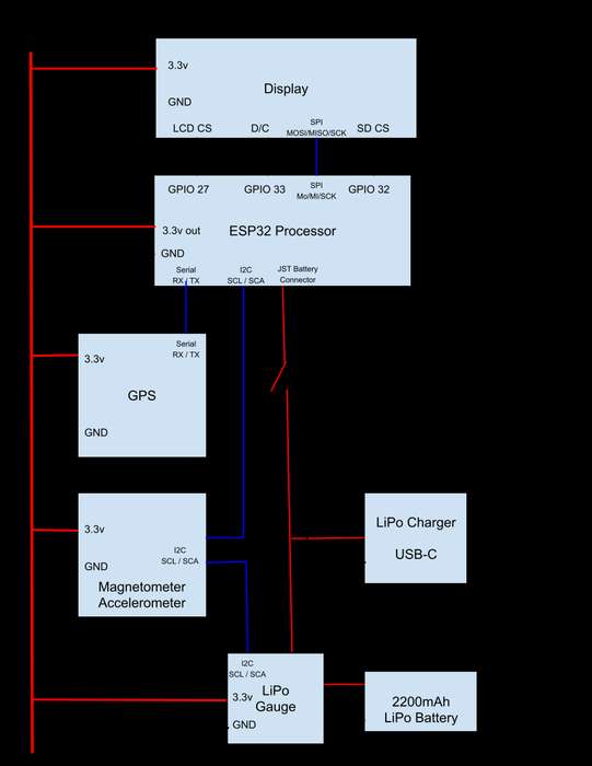
To read the data from the sensors, do the calculations and output information to the screen I chose an ESP32 module. There are a lot of functions and features in the ESP32 that are not used in this project but I had used it in other projects and felt comfortable that it could do the job.
The display is 240 x 320 pixels. It includes an integrated micro SD card holder. I used a SD card in this slot to hold bitmaps of the static screens. Reading these bitmaps and displaying them simplified getting static information on the screen.
In order to orient the compass rose display we need to know how the box is oriented with respect to magnetic north. I used a magnetometer for this purpose. The module used also includes a 3 axis accelerometer. To make accurate magnetometer measurements the module needs to be fairly level. The tri axis accelerometer can be used as a leveling device with appropriate software. Figuring out how to allow for some tilt was interesting since perfect level is hard to achieve.
To find the direction of home along with the distance we must know the current location of the box. This is achieved with a GPS module. With the location data from the GPS along with a hard coded location for home and some trigonometry we can produce a direction (bearing) and distance between the two points.
Once we have all the data then the graphics work must be done to present the information graphically. There is also a text based display screen shown to present the detailed data. This screen also shows other information available from the GPS such as current altitude, UTC time and date.
I wanted the project to be portable so I used battery power. It is typically only turned on for a few minutes at a time. I added a module to provide the current state of the battery. I wanted to allow the battery to charge while the device was powered down so I added a Lipo battery charging circuit and did not use the charger on the main processor module.
Step 2: Wiring / Breadboard
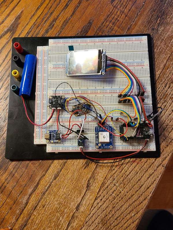
The bread board version shown was used for testing the hardware and most of the software development.
The other pictures show the build up of the internal chassis. Most of the electronics are mounted on 2 pieces of perma-proto board.
The ESP32 board and GPS module are on a half length perma-proto board. I had to add 2 new mounting holes on one end of this perma-proto board to avoid using the mounting hole right under the usb connector on the ESP board.
The power management modules (charger, gauge,JST connector) are mounted on a quarter length perma-proto board.
The magnetometer is mounted directly to the plywood base,
All mounting to the plywood is done using 2.5mm black nylon standoffs. The standoff nuts are counter sunk into the plywood to allow the plywood to sit flush in the bottom of the box.
The battery gauge and magnetometer use the I2C bus to communicate with the processor. These Adafruit modules have what they call Stemma QT connectors. These are essentially I2C and power connections.
The GPS module uses serial UART communications to connect to the processor. These 4 connections are made with solid hookup wire right on the perma-proto board.
The display and SD card uses SPI. These connections are made with a ribbon of breadboard wires with male pins on them. They were soldered directly to the TFT display and then to the perma-proto board with the ESP32.
Two pins for the power switch connection are soldered to the board that carries the power modules. A micro switch is mounted to the inside of the back of the box. A hole in the bezel and a small piece of wood mounted inside the back of the lid allows the switch to actuate as the lid opens.
Connection List:
TFT Display:
ESP32 Pin – TFT Pins
GPIO 27 – LCD CS (Chip Select)
GPIO 33 – Data / Command (D/C)
GPIO 32 – SD Card CS / SDCS
Not connected – Back light
SCK – SCK
MOSI – MOSI
MISO – MISO
Not connected – Reset
3.3v buss – VIN
GND buss – GND
GPS Module:
ESP32 Pin – GPS Pin
3.3v buss – VIN
GND buss – GND
RX – TX
TX – RX
Power Pins:
ESP32 – Power Buss
3V out – 3.3v buss
GND – GND buss
I2C Stemma connector:
ESP32 Pin – Wire Color
3.3v buss – Red
GND buss – Black
SCL – Yellow
SDA – Blue
Step 3: Box Modifications
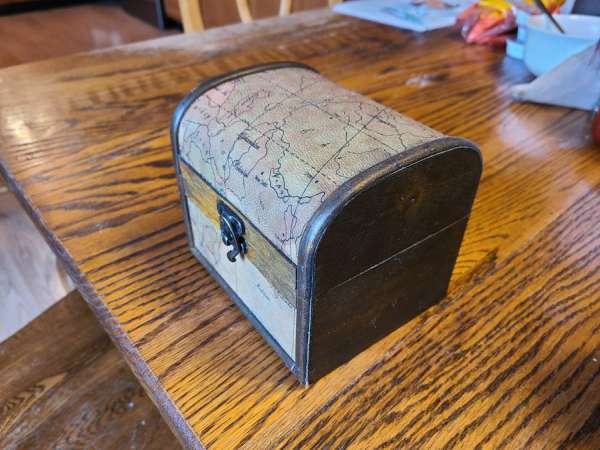
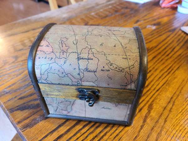
I searched a lot for an appropriate box to contain this project. Ebay, Etsy, local stores such as Michaels and Hobby Lobby. After buying an unfinished box at Michaels I decided to try this box from Hobby Lobby. It measures 5 3/4″ (146mm) x 5″ (127mm) x 5 1/8″ (130mm) the bottom section where all of our electronics live is 2 3/4″ (70mm) deep.
I decided that I wanted to make the electronics removable from the box. Like stereos and TVs of years past, the electronics are mounted on a chassis that is relatively easy to remove from the cabinet.
First I added the two 1/2″ (13mm) x 1/2″ (13mm) rails inside each end of the box. I used a small piece of the basswood material that the bezel is made of to space the rails down from the top edge of the box sides. This allows the bezel to fit flush inside the bottom part of the box.
The inner chassis base is a piece of 1/4 inch (6mm) thick plywood. I cut it to just fit in the bottom of the box but I had to trim the length slightly in order to get it into the box past the rails that support the bezel.
I used a hole saw to make a 30mm hole in the back of the box for the USB charge connector.
1/8th inch thick basswood bezel.
The chassis is held in the box by 4 nylon 8-32 screws and brass ball nuts that also act as feet for the box. I clamped the chassis plywood base into the box and drilled four holes for these screws.
Aging the brass fasteners?
Staining the visible wood parts.
Step 4: Software
These are the Adafruit libraries I used to make my life much easier.
#include "Adafruit_LC709203F.h"     // Library for battery gauge
#include <wire.h>                   // I2C Library
#include <adafruit_sensor.h>        // Generic Library for sensors (LSM303AGR)
#include <adafruit_lsm303agr_mag.h> // Library to talk to the magnetometer / accelerometer
#include <adafruit_lsm303_accel.h>  // Magnetometer / Accelerometer
#include "SPI.h"                    // Communication Library used for the display
#include "Adafruit_GFX.h"           // Graphics Library
#include "Adafruit_ILI9341.h"       // Display Library
#include <sdfat.h>                  // SD card & FAT filesystem library
#include <adafruit_spiflash.h>      // SPI / QSPI flash library
#include <adafruit_imagereader.h>   // Image-reading functions
#include <adafruit_gps.h>           // Library to talk to the GPS module
#include "structures.h"             // My structure definition to move data between
I created this data structure that is used to pass data between all the functions in the program. I called it BEARING.
typedef struct {
  int Bearing;         // 0 to 359, negative = unavailable, Relative to North
  float Distance;      // round to .0, If no bearing no distance
  int North;           // 0 to 359
  float Lat;
  float Lon;
  float Altitude;
  int SatQty;
  float Quality;
  int Diminsion;
  String Time;
  String Date;
  float Battery;
} BEARING;
The following is the general flow of the program. You can see the function names and a short description of what they do.
Set up section:
Display a Splash screen “Pilot Ridge Enterprises” with a logo and a couple of other screens with personal and Lord of the Rings references with a few seconds delay between them. These are bitmaps created to fit the TFT size and stored on the SD card.
The GPS has a battery backup to keep acquisition times down. However it still takes a while so displaying these screens is killing time for GPS acquisition.
Begin The Main Loop.
Function: BEARING readCompass(BEARING)
The leveling routine is a loop. If the box is not level then we display a bullseye bubble level and “Please level the box” message, we loop and show message until the box is level. No message is displayed if the box is already level, this loop just ends.
Then we read the compass bearing to find North. Average several compass readings. Return the current orientation of the box.
Function: BEARING readBatt(BEARING)
Check the battery level. Return both the voltage and current state of charge.
Function: BEARING readGPS(BEARING)
If the GPS has a signal locked get lat, lon, altitude, #sats, quality, time, date. Calculate the bearing and distance.
Function: displayCompass(BEARING)
Display oriented compass rose with “Waiting for GPS acquisition” or bearing arrow. Show distance if GPS data is available. This function is complicated and draws a lot of filled triangles on the TFT display. Lots of trigonometry.
Function: ShowText(BEARING)
The text screen display shows the detailed data that has been collected.
Battery state
Bearing
UTC Time
Distance
Date
Altitude
Current Lat
Current Lon
# satellites
Fix quality
End of the Main Loop.
Source: Always Know Where Home Is At