
Summary of Analog to Digital Converter AVR C Programming
This tutorial demonstrates programming an Atmel AVR Mega168 microcontroller to read analog signals using the ADC peripheral. The project uses a voltage divider circuit (trimpot) connected to port RC0 to control LED shifting speed on PORTD, illustrating real-time analog-to-digital conversion and processing in C.
Parts used in the AVR Analog Signal Reading Project:
- AVRJazz Mega168 Learning Board
- ATMega168 Microcontroller
- 8 Blue LEDs
- User Trimpot
- STK500 v2.0 Bootloader
- STK500 or AVRISP Programmer
- Atmel AVR Studio 4 IDE
- AVR-GCC Compiler
One of the important features in today’s modern microcontroller is the capability of converting the analog signal to the digital signal. This feature allows us to process the analog world easily such as temperature, humidity, light intensity, distance, etc; which usually captured by electronics sensor and represent it on the change of voltage level.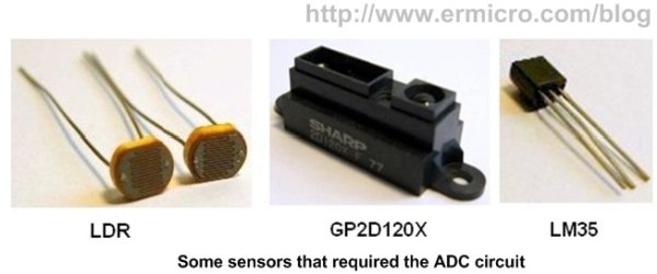
In this tutorial we will show you how to program the Atmel AVR microcontroller for reading the analog signal. We will use the AVRJazz Mega168 board as our learning platform and let’s start the fun by pasting this code to your AVR Studio 4 editor:
//***************************************************************************
//  File Name	 : ADC.c
//  Version	 : 1.0
//  Description  : Using AVR ADC Peripheral
//  Author	 : RWB
//  Target	 : AVRJazz Mega168 Learning Board
//  Compiler     : AVR-GCC 4.3.0; avr-libc 1.6.2 (WinAVR 20080610)
//  IDE          : Atmel AVR Studio 4.14
//  Programmer   : AVRJazz Mega168 STK500 v2.0 Bootloader
//               : AVR Visual Studio 4.14, STK500 programmer
//  Last Updated : 21 March 2008
//***************************************************************************
#include <avr/io.h>
#include <util/delay.h>
int main(void)
{
   unsigned char chSign,chEye;
   unsigned int iDelay;
   DDRD = 0xFF;                  // Set PORTD as Output
   chEye=0x01;                   // Initial Eye Variables with 0000 0001
   chSign=0;
   // Set ADCSRA Register in ATMega168
   ADCSRA = (1<<ADEN) | (1<<ADPS2) | (1<<ADPS1);
   // Set ADMUX Register in ATMega168
   ADMUX=0;
   for(;;) {                     // Loop Forever
     // Start conversion by setting ADSC in ADCSRA Register
     ADCSRA |= (1<<ADSC);
     // wait until conversion complete ADSC=0 -> Complete
     while (ADCSRA & (1<<ADSC));
     // Get ADC the Result
     iDelay = ADCW;
     if (iDelay < 1) iDelay=1;
     // Display the LED
     if (chSign == 0) {
       PORTD=chEye;
       _delay_ms(iDelay);          // Call Delay function
       chEye=chEye << 1;
       if (chEye >= 0x80) chSign=1;
     } else {
       PORTD=chEye;
       _delay_ms(iDelay);          // Call Delay function
       chEye=chEye >> 1;
       if (chEye <= 0x01) chSign=0;
     }
   }
   return 0;	                    // Standard Return Code
}
// EOF: ADC.c
Before building the program first configure the frequency to 11059200 Hz from menu Project -> Configuration Option. Rebuild and down load the program to the AVRJazz Mega168 board by first putting the board in programming mode and select STK500 or AVRISP programmer from AVR Studio 4. For detail explanation of using this board feature you could go to AVRJazz Mega168 Learning and Development Board or Starting Atmel AVR C Programming Tutorial.
While running the program, the 8 blue LEDs start to shifting back and forth to the left and right; try to adjust the user’s trimport by turning it to the left or right and you could see the speed of LED shifting will vary.
The user’s trimport basically work as a voltage divider circuit and provide voltage input level to the microcontroller analog port (RC0) by changing the trimmer; it will change the voltage input level to the analog port.
For the ADC peripheral programming on the Atmel AVR Mega168 microcontroller we will focus on these 4 important registers (special memory location on the Atmel AVR microcontroller families):
For more detail: Analog to Digital Converter AVR C Programming
-
How do you configure the frequency for this program?
You must configure the frequency to 11059200 Hz from the menu Project - Configuration Option. -
What hardware is used as the learning platform?
The AVRJazz Mega168 board serves as the learning platform for this tutorial. -
How does the trimpot affect the LED behavior?
Turning the trimpot changes the voltage input level, which varies the speed of the LED shifting. -
Which register controls the ADC enable and prescaler settings?
The ADCSRA Register is used to set the ADC enable bit and prescaler bits ADPS2 and ADPS1. -
How is the ADC conversion result retrieved?
The result is retrieved by reading the ADCW variable after the conversion completes. -
Where is the voltage input connected on the microcontroller?
The trimpot provides voltage input to the microcontroller analog port RC0. -
What happens if the ADC delay value is less than 1?
If the iDelay value is less than 1, the code sets it to 1 to ensure proper timing. -
Which compiler version is specified for this code?
The code specifies the use of AVR-GCC 4.3.0 with avr-libc 1.6.2.
