Summary of Arbitrary Wave Generator With the Raspberry Pi Pico
The article describes converting an Arduino-based arbitrary waveform generator (AWG) to a Raspberry Pi Pico using the RP2040 microcontroller. By leveraging the Pico’s DMA and PIO peripherals, the author streams waveform arrays to an 8-bit R2R DAC at up to 125 Msps—over 300× faster than the Arduino version—using MicroPython. Construction, resistor selection, software setup, waveform options, and performance limits (high output impedance, low drive) are discussed, plus code comments and improvement ideas like higher resolution, buffering, amplification, and UI additions.
Parts used in the Arbitrary Wave Generator With the Raspberry Pi Pico:
- Raspberry Pi Pico microcontroller with male pin headers
- 5x7 cm prototype board
- 2 × 20-pin female pin headers
- 23 resistors of identical value (near 2 kOhm), used to form R and 2R for an 8-bit R2R DAC
- 2 male header pins (signal and ground)
- Probe clips or crocodile clips (for connections)
Just two weeks ago, the pico, a new microcontroller, the pico, was released by the Raspberry Pi Foundation, well known for the incredibly successful series of Raspberry Pi single-board computers. The new microcontroller uses a brand new chip, designed in-house, the RP2040. It has two 32-bit cores running by default at 125MHz. It has been criticised for not having Wifi or Bluetooth, and no hardware floating point math. But it has a very fast internal bus and powerful peripherals. It has been designed for makers and has very strong support: it was released with 6 detailed datasheets and a beginner’s guide book, which is available free of charge as pdf. Best of all, it is cheap at $4. I got 5 for under 30EUR including shipping.
As a test I wanted to see if any of my previous projects based on the Arduino Uno/Nano could benefit from a remake with this much more powerful board: After all it has 4x the bus width, 8x the clock frequency, 130x the RAM, and is more than a decade more modern. My choice fell on the Arbitrary waveform generator (AWG). With the Arduino, I managed to squeeze out 381ksps, since every sample update took 42 instruction cycles, mostly because updating a 32-bit phase counter takes a quadruple loop with an 8-bit CPU. My expectation was that it should be possible to improve this by a factor 8 just from clock speed and maybe another factor 2 because the new board is 32-bit. However, after reading selected parts of the 637-page datasheet of the new RP2040 chip, I realised it might be possible to update every single clock cycle! Just by initialising 2 peripherals, the DMA (Direct Memory Access) and the PIO (programmable Input/Output), an array can be cyclically streamed to the output pins.
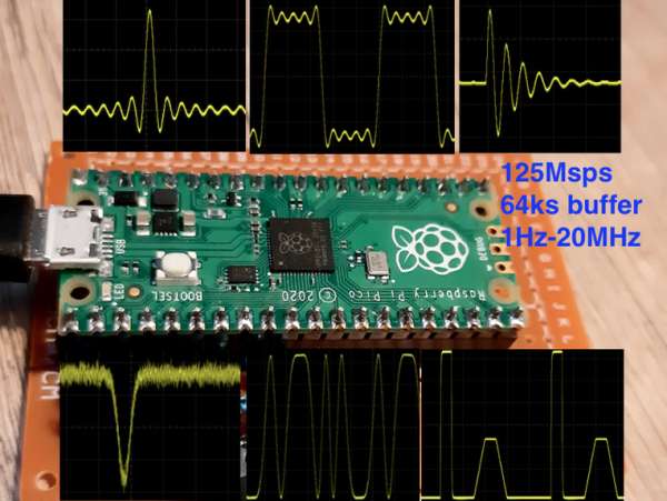
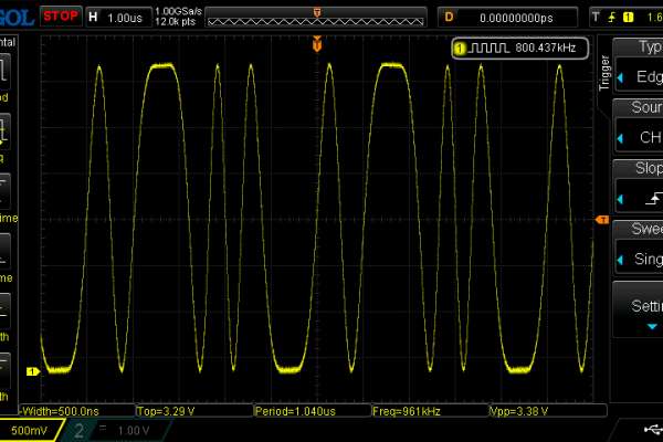
Indeed, it works, and the increase in speed with the Arduino is more than a factor 300, from 381ksps to 125Msps. That is similar to serious lab-AWGs, which cost ~100EUR for budget models. There is no attempt here to provide a buffer or amplifier for the produced signal, it is beyond my skills and my equipment to come up with a buffer/amplifier beyond the 10MHz range. The produced signal is thus rather weak, with an output impedance of ~1kOhm, and a maximum current draw of ~1mA. Suggestions for a buffer/amplifier are welcome in the comments! There is no attempt either to provide a dedicated user interface in terms of a screen, buttons, rotary encoders etc. That adds cost and complexity. I found it is much more convenient and much more powerful to set the requested waveform in the micropython code itself!
For comparison, several instructables (e.g. here, here and here) describe how to make a function generator based on the dedicated AD9833 chip. This chip runs at 25Msps and can generate only 3 predefined waveforms: sine, triangle and square. The pico is 5x faster and can generate any possible wave that fits in an array, up to many thousands of points.
Supplies:
Required materials:
- Raspberry pi pico microcontroller with male pin headers
- 1 5x7cm prototype board
- 2 20-pin female pin headers
- 23 resistors of identical value, near 2kOhm
Step 1: Construction of the R2R DAC
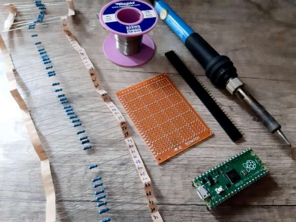
The pico itself cannot produce analog signals, it does not have a digital-to-analog converter (DAC). But they are simple to build from resistors. We use here the classic R2R DAC. An 8-bit DAC requires 7 resistors of value R and 9 resistors of value 2R. The actual value of R is not critical, but it is essential that all ‘R’ resistors have the same value and that all 2R resistors have double that value. In practice, this is best achieved by using 23 resistors of 2R, and putting 7 pairs of them in parallel to create the 7 ‘R’ resistors. Resistors with a power rating of 0.25W and a tolerance of 1% are cheap in packs of 100, and that is what I recommend to use. I had an unused pack of 2kOhm resistors. I think any value of R in the range 1kOhm-10kOmh will be fine. Smaller values will draw more current than the Pico can provide and larger values result in poor performance because there is too little current to counteract parasitic capacitance and/or inductance at high frequencies.
I numbered all the resistors, measured their values and put them in a spreadsheet. None differed by more than 1% from the nominal value, but by selecting I could reduce the effective spread from 1 percent to 1 per mille. For the ‘2R’ resistors I picked a value near the mean of which there were at least 9, which happened to be the value 2000. Then I picked 7 pairs that were equally distant from the value 2000, for example 3 pairs of 1998+2002 Ohm and 4 pairs of 1997+2003 Ohm. In parallel, equal but opposite deviations cancel!
Solder the female headers to the prototype board such that the pico fits comfortably. Now solder the resistors according to the provided schematics and pictures. Note that the resistors are mounted vertically only to save space. Feel free to mount them horizontally if space allows. The board layout is done with KiCad. I did not make a PCB, but a PCB layout helps to solder effectively on the 5x7cm prototype board. Note that my build differs slightly from the KiCad design, I made some improvements to the design after soldering it up.
At the end I added to two male header pins: one for the signal and one for ground. Probe clips and crocodile clips attach well to them.
Step 2: Uploading the Software and Run
The pico can be programmed in C or micropython. Using micropython is much easier since you don’t have to install the ‘C-SDK’. Micropython may be 100x slower than C, but here it doesn’t matter. All the code does is making an array with a waveform and then instructing the peripherals to stream that array to the output pins. The CPU is idle and free to perform other tasks.
Make sure your pico has the micropython UF2 file uploaded. I used version rp2-pico-20210205-unstable-v1.14-8-g1f800cac3.uf2. Version 1.13, which was originally provided on release day, misses the ‘uctypes’ module. I used the Thonny IDE to upload the python script, I had never heard of that before but it works well, at least for small scripts like this.
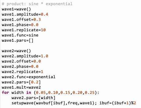
The code as is will run though a few hundred example waves (see video at step 1). To modify this, scroll to line 155 and set up your own wave.
There are 6 basic pulse shapes: sine, pulse, gaussian, sinc, exponential and noise. The sine has no extra parameters, but the pulse has 3: risetime, uptime and falltime. Gaussian, sinc and exponential have one parameter, which determines their width, and noise has one parameter, which determines the pdf of the output values, from 1 (flat) to 8 or larger (nearly gaussian).
A wave will have a shape, but also amplitude and offset. The shape can be replicated within a period, which increases its frequency. That way, operations like summing or multiplying can be done with waves of different frequencies. A non-zero phase shift can also be set, but its effect is only noticeable when combining waves.
Waves can be combined by either summing, multiplying or applying a phase modulation with another wave. The resulting combined wave can then be added, multiplied or modulated with another basic or complex wave. The screenshots and video show just a few examples of how complex shapes can be made.
There is only one value for the frequency, even when combining waves. Operations are not performed on-the-fly by the CPU, but stored in a buffer and played by the DMA/PIO. The ‘duplication’ keyword however does allow for a shape to fill at double, tripe, quadruple etc values of the (base) frequency.
The buffer size (value of maxnsamp) determines how complex the shape can be made, and how accurate the frequency can be set. For simple waves, like single sine or wide pulses, 1024 samples may be sufficient. A buffer size of 65536 (64kB) is the practical maximum. Filling the buffer may take 20-60s at that size!
Step 3: Comments About the Code
I admit the code looks obscure: most of it is based on direct register access, and require studying the 637-page datasheet of the RP2040 chip to understand. But I’ll try to explain the thought behind it.
The crucial peripheral is the so-called Direct Memory Access (DMA) module of the chip. The DMA can be instructed to perform block copies between memory and peripherals without requiring the attention of the CPU. Really, I had no clue this existed just 2 weeks go either! It is like having an assistant whom you tell to do shopping for you!
Anyway, this DMA is being told to transfer the contents of the array with the waveform to another peripheral (the PIO) which will put the values on the output pins. One complication is that this DMA needs to do this cyclically, and without interruption. For that, a second DMA channel is instructed to reconfigure and restart the first DMA channel as soon as it is done. This is called ‘chaining’. So channel 0 does the transfer, and passes the stick on to channel 1. But channel 1 immediately tells channel 0 to restart. You might expect a delay in this swapping between the channels, but that delay is absorbed in buffers: the DMA transfers 32-bit words, while the PIO only ‘eats’ 8-bit bytes. So the PIO still has some snacks in its buffer while the DMA is losing 1 or 2 cycles to start over again. I am amazed by the engineers and scientists who came up with such intricate hardware!
The DMA cannot control the pins directly, but there is something better: the pico has 2 Programmable Input/Output (PIO) units, which have 4 processing units themselves, (called ‘state machines’). They are really 8 tiny microcontrollers inside the microcontroller itself. Here, only 1 state machine is used, and it is programmed with a single command (would this qualify for a Guinness World record of smallest computer program?) The command is ‘out(pins,8)’ which instructs the state machine to pass 8 bits from its buffer to the output pins. Wrapping is implied, so the state machine just keeps doing this single command, every clock cycle. As the 8 bits are shifted to the pins, the buffer will request to be refilled by the DMA when 32 bits have been consumed.
And that’s all. So the code consists of
- The configuration of the DMA
- The configuration and programming of the PIO
- The filling of the array with the waveform
- Starting up the DMA.
At that moment the waveform is produced and the CPU’s of the pico are free for other tasks. There will be data traffic on the bus, but the pico has a highly parallel bus structure, and I expect no noticeable slow-down.
Step 4: Ideas for Improvement
I posted this instructable a bit prematurely to demonstrate the capabilities of this new microcontroller. I hope it will motivate some of you to get a board and try out its new features.
For this AWG project I have several ideas on how to improve it:
- It might very well be possible to have higher resolution (10 or 12 bit) and/or a second channel.
- The RP2040 can be overclocked to 250 MHz or more, resulting in 250Msps AWG
- Sweeps of frequency or other parameters can be implemented in the python code after setup.
- A real AWG needs a buffer and/or amplifier to reduce the output impedance and extend the voltage swing.
- A well-designed PCB and SMD resistors might reduce parasitic capacitance or inductance and improve the bandwidth.
- A screen and buttons, or a touch-screen could make it into a self-confined apparatus, like the commercial devices.
Source: Arbitrary Wave Generator With the Raspberry Pi Pico
- What microcontroller is used in this AWG project?
The Raspberry Pi Pico using the RP2040 chip is used. - Can the Pico produce analog output directly?
No, the Pico has no built-in DAC; an external R2R resistor ladder DAC is used. - How is high-speed waveform output achieved?
By initializing the DMA to transfer waveform arrays to the PIO state machine which outputs 8 bits per clock cycle. - What sample rate was achieved compared to the Arduino version?
The Pico implementation reached 125 Msps, over 300 times faster than the Arduino's 381 ksps. - What resistors are required for the 8-bit R2R DAC?
An 8-bit DAC needs 7 resistors of value R and 9 resistors of value 2R; the author used 23 equal-value resistors arranged to form these. - Which programming language is recommended for this project?
MicroPython is recommended for ease; the project uses MicroPython and Thonny IDE. - What are the limitations of the raw output signal?
The produced signal has high output impedance (~1 kOhm) and low current drive (~1 mA), and no buffer or amplifier is provided. - How large can the waveform buffer be?
The practical maximum buffer size is 65536 samples, and filling large buffers can take 20–60 seconds. - Are multiple waveform shapes supported?
Yes; six basic shapes are provided: sine, pulse, gaussian, sinc, exponential and noise, with parameters for many shapes. - Can waves be combined or modulated?
Yes; waves can be summed, multiplied, or used for phase modulation, and combinations are stored in the buffer and played by DMA/PIO.