Summary of AT89S52 DS1620 THERMOMETER CIRCUIT (LCD DISPLAY)
This project utilizes an AT89S52 microcontroller and a DS1620 temperature sensor to display ambient temperature on a 128×64 graphic LCD. The system triggers a red LED when the temperature exceeds 25°C and illuminates a green LED when it drops below this threshold. A 12 MHz crystal oscillator provides the necessary clock signal for operation, while the microcontroller processes 9-bit data from the sensor.
Parts used in the AT89S52 DS1620 Thermometer Circuit:
- AT89S52 Microcontroller
- DS1620 Temperature Sensor
- 128 × 64 Graphic LCD
- Red LED
- Green LED
- 12 MHz Crystal Clock Oscillator
This project gave ds1620’n given as a result of the digitally using AT89S52 microcontroller is a graphic display of temperature information of the LCD screen. Moreover, the circuit ambient temperature when it reaches a…Electronics Projects, AT89S52 DS1620 Thermometer Circuit (LCD Display) “8051 example, avr project, keil example, microcontroller projects, “
This project gave ds1620’n given as a result of the digitally using AT89S52. Microcontroller is a graphic display of temperature information of the LCD screen.
Moreover, the circuit ambient temperature when it reaches a temperature above 250C is no longer a red LED lighting in the same way as the ambient temperature drops below 250C. A green LED lights up to notify user intended. 12 MHz crystal clock oscillator circuit to set the clock oscillator is used.
DS1620 is a temperature sensor and also the legs 8 is used as thermostat. Temperature is given as 9-bit data.
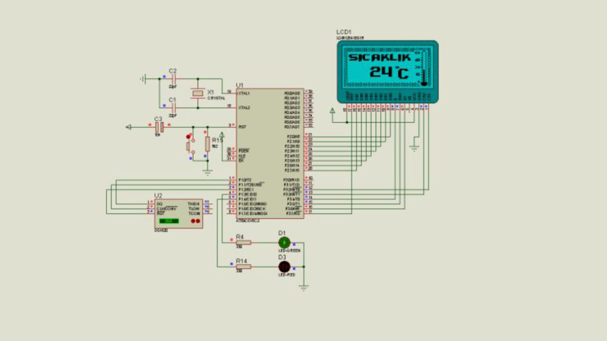
Demonstration of circuit temperature is obtained by using a 128 × 64 graphic LCD. LCD’s D0, D1, D2, D3, D4, D5, D6, D7 is provided with a connection to microcontrollers. Second intervals in the program I set the LCD also seems my school ID.
THERMOMETER CIRCUIT SCHEMATIC
AT89S52 DS1620 Thermometer Circuit keil source: https://320volt.com/en/ds1620-at89s52-isi-olcumu-glcd-termometre/ code and proteus isis simulation schematic files:at89s52-ds1620-thermometer-circuit-lcd-display.rar Prepared by: @Sükriye KAYA Thanks to the People
Alternative File Download LINK list (in TXT format): LINKS-4761.zip
- What is the primary function of the DS1620 in this circuit?
The DS1620 acts as a temperature sensor and its eighth leg functions as a thermostat. - How does the circuit indicate high temperatures?
A red LED lights up when the ambient temperature rises above 25 degrees Celsius. - What happens when the temperature drops below 25 degrees Celsius?
A green LED lights up to notify the user that the temperature has fallen below the threshold. - What type of display is used to show temperature information?
A 128 by 64 graphic LCD screen is used for the digital display. - How many bits of data does the temperature sensor provide?
The temperature is provided as 9-bit data. - What clock frequency is used for the oscillator circuit?
A 12 MHz crystal clock oscillator is used to set the clock. - Which microcontroller pins connect to the LCD data lines?
LCD data lines D0 through D7 are connected directly to the microcontroller.