Summary of AT89S52 THERMISTOR CIRCUIT THERMOMETER LCD DISPLAY
This article describes an NTC Thermistor Thermometer project using the AT89S52 microcontroller and HIH-3160 humidity sensor to display temperature and humidity data on an LCD. The circuit supports ADC options like LTC1298 or MCP3202, utilizes P0 for the LCD bus, includes an optional switch (SW1), and allows connection of additional sensors via J2 with a 0 to +5V input range.
Parts used in the AT89S52 Thermistor Thermometer:
- AT89S52 Microcontroller
- NTC Thermistor
- Honeywell HIH-3160 Relative Humidity Sensor
- LCD Display
- LTC1298 or MCP3202 ADC
- P0 Port Interface
- SW1 Key Switch
- J2 Connector
NTC Thermistor Thermometer based on AT89S52 circuit and HIH 3160 humidity sensor humidity and temperature information is given. Display LCD display circuit and there are two versions of the C source code and schema… Electronics Projects, AT89S52 Thermistor Circuit Thermometer LCD Display “avr project, microcontroller projects, “
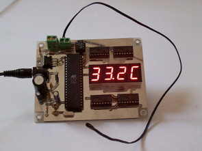
NTC Thermistor Thermometer based on AT89S52 circuit and HIH 3160 humidity sensor humidity and temperature information is given. Display LCD display circuit and there are two versions of the C source code and schema files have been prepared by Orcad.
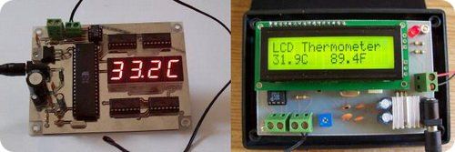
Thermistor Thermometer: LCD version: The ADC and thermistor circuits are quite the same as the 1st version. The ADC can be LTC1298 or MCP3202. Now with this design, P0 is used to interface LCD bus. SW1 is optional key switch. Since the number of I/O port are not many, we then can replace the 40-pin MCU with 20-pin MCU easily. J2 is available for connecting another sensor. The input range is 0 to +5V. HIH-3160 Honeywell Relative Humidity Sensor
Source: AT89S52 THERMISTOR CIRCUIT THERMOMETER LCD DISPLAY Thermistor Thermometer LCD Display Alternative link: at89s52-thermistor-thermometer-lcd-display.rar
- What components are used to measure humidity and temperature?
The project uses an NTC Thermistor and a Honeywell HIH-3160 Relative Humidity Sensor. - Which microcontroller is the basis of this circuit?
The circuit is based on the AT89S52 microcontroller. - Can the design use different ADC chips?
Yes, the ADC can be either the LTC1298 or the MCP3202. - How is the LCD connected in this design?
The P0 port is used to interface the LCD bus. - Is the key switch mandatory for the circuit?
No, SW1 is an optional key switch. - What is the input voltage range for the system?
The input range is 0 to +5V. - Can another sensor be connected to the board?
Yes, J2 is available for connecting another sensor. - Is it possible to replace the current microcontroller with a smaller one?
Yes, since the I/O ports are limited, the 40-pin MCU can be replaced with a 20-pin MCU.