
Summary of Atmega168 TV-B-Gone
This article guides beginners on building a compact, Arduino-based TV-B-Gone using an Atmega168 chip. The project involves designing a custom PCB to fit inside a Muji box with a 9V battery, modifying software from Ken Shirriff's blog for the specific IC, and utilizing a laser-printed toner transfer method for circuit fabrication.
Parts used in the Atmega168 TV-B-Gone:
- An ATmega168 microcontroller with socket
- A temporary NO button
- A little switch
- A 5V voltage regulator L7825CV
- A 16000 hz quartz
- An NPN transistor PN2222A
- Two coloured LEDs
- An IR LED
- Resistors: 220ohm, 10ohm, 1Kohm, 10Kohm, 47ohm
- Caps: 10uF, 22pF, 22pF
- A 9V battery with connections
- A convenient box (Muji)
Yes, I know what you are thinking: “oh no, please not another TVBGone…”
Anyway, this instructable is for the newbies as me which are still experimenting with Arduino, and prefer to program an Atmega168 in Arduino than an AtTyny85 with other methods.
This circuit is based on Mitch Altman’s TVBGone and on Ken Shirriff’s blog where the software has been modified to match Arduino IC. I then decided to move the programmed Atmega on a dedicated pcb, and make everything fit in a transparent box with a 9V rechargeable battery.
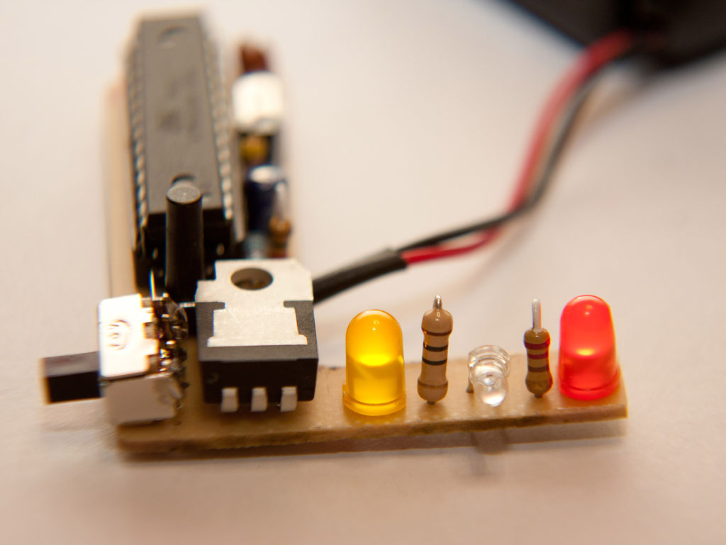
Step 1: choose the box
My TVBGone uses only a little IR LED, so it shouldn’t be much powerful, anyway it’s enough to turn off the unwanted tv with ads which had born as mushrooms anywhere in any station here in Milan, the difference is that mushrooms are very quiet…

Step 2: the BOM
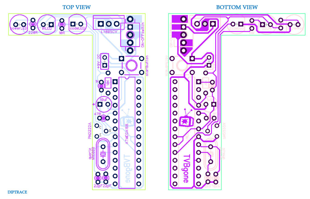
In pdf you will find the traces to transfer on the copper board and the top view with components position and values. Next is the bill of materials.
- an ATmega168 with socket
- a temporary NO button
- a little switch
- a 5V voltage regulator L7825CV
- a 16000 hz quartz
- an NPN transistor PN2222A
- two coloured LEDs
- an IR led
- the following resistors: 220ohm, 10ohm, 1Kohm, 10Kohm, 47ohm
- the following caps: 10uF, 22pF, 22pF
- a 9V battery with connections
- a convenient box
- a damned annoying television always turned on

Step 3: the pcb printing…
As usually, after cutted the copper board at the (almost) right dimension, I’ve laser-printed the traces on a glossy paper and I transfered them on the board with an iron. For this process you could follow this instructable “the TIRR (very simple Timelapse IR Remote)” or this other one “BBB (Bothersome Blinker for Bikes)” where it’s good explained.
When you’ve transfered the scheme on the copper and cleaned it from the paper, check meticulously the continuity of the single traces, and try to fill with a fine permanent marker every interruption. After that you’re ready to etch your pcb.
Step 4: …and etching
- Who is this project intended for?
This project is designed for newbies who prefer programming an Atmega168 in Arduino rather than using other methods with an AtTyny85. - What is the basis of the circuit design?
The circuit is based on Mitch Altman's TVBGone and Ken Shirriff's blog, with software modified to match the Arduino IC. - How can I find the code for this project?
The code attached is the same one available for download from Ken Shirriff's blog. - Which program was used to create the schematic?
The schematic was created using Diptrace, a free PCB program for up to 250 pins. - What method is recommended for transferring traces to the copper board?
The author recommends the laser-printed toner transfer method using glossy paper and an iron. - What should be done if there are interruptions in the traces after cleaning?
You should fill every interruption with a fine permanent marker before etching the PCB. - Why were very thin traces used in the design?
Thin traces were used to pass between the pins and simplify the manual routing work. - Does the device require a powerful IR LED?
No, the device uses only a little IR LED which is enough to turn off unwanted TVs.
