Summary of ATMega32 AVR USART C programming examples
The article shows AVR C USART examples for ATmega32: (1) echoing up to 15 received characters back to the host when ENTER is pressed, and (2) using ANSI C string functions (strcmp) to parse commands like rl1On, rl1Off, allOn, allOff to toggle PORTC outputs. Code, schematic, and downloadable examples are provided; LED indicators on PORTC illustrate received data or relay-equivalent outputs.
Parts used in the ATMEGA32 AVR USART Examples:
- ATmega32 microcontroller
- 16 MHz crystal oscillator (or clock source configured for 16 MHz)
- LEDs (connected to PORTC as indicators)
- Resistors for LEDs
- PC with USART terminal software (host PC)
- UART/USART serial connection (e.g., RS232 level shifter or USB-to-TTL adapter)
- Power supply for the microcontroller
- Prototyping board or custom PCB
In the previous article, I discussed the USART module of the ATMega32 device, providing some practical examples. In this article, I will present additional USART examples that involve AVR C programming techniques. These techniques include creating conditions based on received characters and utilizing the ANSI C string functions library.
In this straightforward illustration, the user transmits a series of characters to the MCU USART module using the host PC’s USART terminal. The MCU monitors these characters and stores them in an array, which can hold up to 15 characters, or a size determined by the programmer.
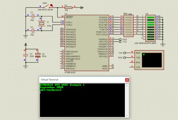
Whenever the user presses the ENTER key (with an ASCII value of 0x0D), the MCU concludes the current character storage and promptly sends all the preceding characters back to the host PC terminal.
/*
* uart_example_1.c
*
* Created: 9/30/2020 10:21:10 AM
* Author : aki-technical
* #include <avr/io.h>

#define F_CPU 16000000UL
#include <util/delay.h>

#define uartReady UCSRA&(1<<RXC) void uartInit(unsigned long baud){ unsigned int UBRR; /*Baud rate calculator*/ UBRR=(F_CPU/(16*baud))-1; UBRRH=(unsigned char)(UBRR>>8);
UBRRL=(unsigned char)UBRR;
/*Enable the transmitter and receiver*/
UCSRB=(1<<RXEN)|(1<<TXEN)|(1<<RXEN);
/*asynchronous mode, 8-bit, 1-stop bit*/
UCSRC=(1<<URSEL)|(1<<UCSZ1)|(1<<UCSZ0);
}

void uartTransmit(unsigned char data){
/*Stay here until the buffer is empty*/
while(!(UCSRA&(1<<UDRE)));
/*Put the data into the buffer*/
UDR=data;
}

char uartReceive(){
/*Wait until the buffer is full*/
while(!(UCSRA&(1<<RXC))); /*Get the data ready to use*/ return UDR; } void sendText(char *txt){ while(*txt) uartTransmit(*txt++); } int main(void) { char tmp,i=0; char txt[15]; DDRC=0xFF; uartInit(9600); sendText("ATMEGA32 AVR UART Example 1\n\r"); while (1) { /*If There is a character in the buffer*/ if (uartReady) { tmp=uartReceive(); PORTC=tmp; txt[i]=tmp; i++; } /*If the ENTER Key Is Presented*/ if (tmp==0x0D) { /*Send text back to the terminal*/ sendText(txt); /*Clear the character storage*/ tmp='\0'; /*Clear all the texts*/ while(i>0){
txt[i]='\0';
i--;
}
}

}
}

/
The source code for the program as a whole differs slightly from the previous post, with the exception of a few C code blocks used for processing the received characters.
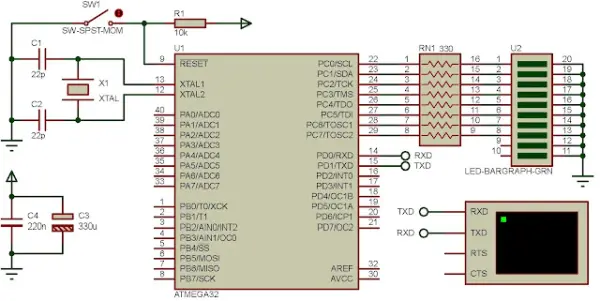
I configured the clock to run at 16 MHz to suit my custom prototyping board. The LED bar graph connected to PORTC serves as an indicator of the received data’s presence.
Click here to download the zip file of this working example.
Using the ANSI C string functions library
This example I use the string compare function from the ANSI C string library function. There are a lot of string processing functions in this library. However I pick up only one’s that only required in this example.
The string compare – strcmp()
int strcmp(char *string1,char *string2);
where,
– string1 is the first string to be compared
– string2 is the second string to be compared
This function returns:
less than zero if string1 is less than string2
greater than zero if string1 is greater than string2
zero if these two string are equal.
Now let move the overall processes of this example. Once the user sends the command the MCU reads the character stored in the USART buffer, and make it a string. Whenever the user enter a new line or ENTER, the MCU start process the string comparison. When the comparison is matched the MCU toggles its corresponding output pin.
Let see the source code.
/*
* uart_example_2.c
*
* Created: 9/30/2020 5:34:08 PM
* Author : aki-technical
#include <avr/io.h>

#define F_CPU 16000000UL
#include <util/delay.h>

#include

#define uartReady UCSRA&(1<<RXC) void uartInit(unsigned long baud){ unsigned int UBRR; /*Baud rate calculator*/ UBRR=(F_CPU/(16*baud))-1; UBRRH=(unsigned char)(UBRR>>8);
UBRRL=(unsigned char)UBRR;
/*Enable the transmitter and receiver*/
UCSRB=(1<<RXEN)|(1<<TXEN)|(1<<RXEN);
/*asynchronous mode, 8-bit, 1-stop bit*/
UCSRC=(1<<URSEL)|(1<<UCSZ1)|(1<<UCSZ0);
}

void uartTransmit(unsigned char data){
/*Stay here until the buffer is empty*/
while(!(UCSRA&(1<<UDRE)));
/*Put the data into the buffer*/
UDR=data;
}

unsigned char uartReceive(void){
/*Wait until the buffer is full*/
while(!(UCSRA&(1<<RXC))); /*Get the data ready to use*/ return UDR; } void sendText(char *txt){ while(*txt) uartTransmit(*txt++); } char tmp,i=0; char txt[15]; /*Some string constants to compare with USART command*/ const char cmp1_on[]="rl1On\r",cmp1_off[]="rl1Off\r"; const char cmp2_on[]="rl2On\r",cmp2_off[]="rl2Off\r"; const char cmp3_on[]="rl3On\r",cmp3_off[]="rl3Off\r"; const char cmp4_on[]="rl4On\r",cmp4_off[]="rl4Off\r"; const char allOn[]="allOn\r",allOff[]="allOff\r"; void clearAll(void){ /*Clear the character storage*/ tmp='\0'; /*Clear all the texts*/ while(i>0){
txt[i]='\0';
i--;
}
}

int main(void)
{

DDRC=0xFF;
uartInit(9600);
sendText("ATMEGA32 AVR UART With C String Library Example\r");
while (1)
{
/*If There is a character in the buffer*/
if (uartReady)
{
tmp=uartReceive();
uartTransmit(tmp);
txt[i]=tmp;
i++;
}
/*ENTER or new line is 0x0D in hex*/
if(tmp=='\r'){
/*Toggling pin PC0*/
if(strcmp(txt,cmp1_on)==0){
PORTC|=(1<<0);
sendText("Relay 1 Turns On.\r");
}
else if (strcmp(txt,cmp1_off)==0){
PORTC&=~(1<<0);
sendText("Relay 1 Turns Off.\r");
}

/*Toggling pin PC1*/
if(strcmp(txt,cmp2_on)==0){
PORTC|=(1<<1);
sendText("Relay 2 Turns On.\r");
}
else if(strcmp(txt,cmp2_off)==0){
PORTC&=~(1<<1);
sendText("Relay 2 Turns Off\r");
}

/*Toggling pin PC2*/
if(strcmp(txt,cmp3_on)==0){
PORTC|=(1<<2);
sendText("Relay 3 Turns On.\r");
}
else if(strcmp(txt,cmp3_off)==0){
PORTC&=~(1<<2);
sendText("Relay 3 Turns Off\r");
}

/*Toggling pin PC3*/
if(strcmp(txt,cmp4_on)==0){
PORTC|=(1<<3);
sendText("Relay 4 Turns On.\r");
}
else if(strcmp(txt,cmp4_off)==0){
PORTC&=~(1<<3);
sendText("Relay 4 Turns Off.\r");
}
/*Overall Controls*/
if (strcmp(txt,allOn)==0)
{
PORTC=0x0F;
sendText("All relays turn on\r");
}
else if (strcmp(txt,allOff)==0)
{
PORTC=0x00;
sendText("All relays turn off\r");
}

/*Clearing all the data*/
clearAll();
}

}
}
*/
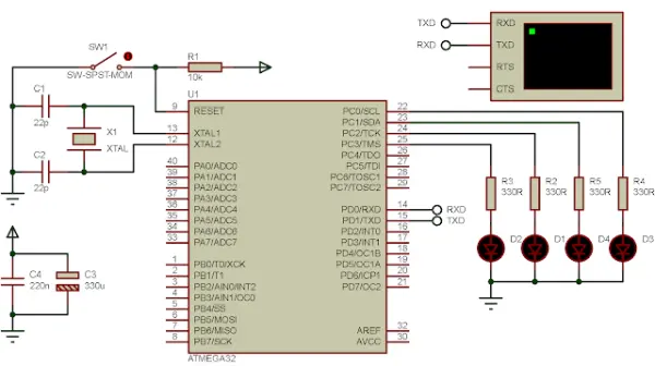
In the source code, I referred to the relay, but the schematic diagram depicts LED as the output devices instead of relays.
- How does the MCU know when to send back received characters?
The MCU waits for the ENTER key (ASCII 0x0D) and then sends all stored preceding characters back to the host. - Can the character buffer size be changed?
Yes, the example uses an array of size 15 but states the size can be set by the programmer. - What indicates received data presence on the hardware?
An LED bar graph connected to PORTC serves as an indicator of received data presence. - How are incoming characters stored in the program?
The MCU reads characters from USART into a char array (txt) and increments an index i for each received character. - Does the example use C string functions for command processing?
Yes, the second example uses the ANSI C string function strcmp to compare received strings to command constants. - What commands are recognized in the strcmp example?
Commands include rl1On, rl1Off, rl2On, rl2Off, rl3On, rl3Off, rl4On, rl4Off, allOn, and allOff (each terminated with carriage return). - What happens when a command matches in the strcmp example?
The corresponding PORTC pin is toggled (set or cleared) and a confirmation text is sent back via UART. - Are the outputs relays or LEDs in the schematic?
The source code refers to relays, but the schematic shows LEDs as the output devices.