Summary of Atmega32-Based Smart Car Parking Solution Using ATMEL STUDIO
The project implements an automatic car parking system using an Atmega32 microcontroller, sensors or switches, LEDs, and a relay to detect vehicle presence and indicate slot status (green for free, red for occupied). The system is developed in Atmel Studio, simulated and tested in Proteus, and uses simple input polling on PORTA with outputs on PORTC plus a delay routine.
Parts used in the Automatic Car Parking System in Atmega32:
- Atmega32 microcontroller chip
- 5-volt VCC (power supply)
- Switch buttons or IR sensors
- 10k ohm resistors (four)
- Ground connection
- LEDs (green and red)
- Relay (single)
- 12-volt DC supply for relay operation
- 2N3904 transistor (for switching relay)
- Proteus (for simulation)
- Atmel Studio (for coding)
The intelligent microcontroller oversees the operation of an automatic car parking system. Utilizing sensors, this project provides real-time feedback through LED displays.
Within the automatic parking system (APS), vehicles are vertically stacked to optimize space. Distinctive system designs facilitate the movement of cars from the entrance to their designated parking slots.
As cars enter the parking area, sensors detect available or occupied slots. The status of these slots is indicated by LED lights or displayed on an LCD screen.
Our project entails crafting an automatic car parking system using Atmega32 via Atmel Studio, subsequently testing its functionality in Proteus.
Firstly, let’s delve into an exploration of the components employed within our project.
Components of Automatic Car Parking System in Atmega32
The project incorporates the following components:
Atmega32 microcontroller chip
5-volt VCC
Switch buttons or optionally IR Sensors for practical implementation
10k ohm resistors
Ground connection
LEDs
Relay
12-volt DC generator for Relay operation
2N3904 transistor for switching operations
Working on Automatic Car Parking System in Atmega32
Within our automatic parking system project, we integrate a sensor. Upon a vehicle’s approach to the parking area, this sensor promptly identifies the vehicle and assesses whether the available slot is occupied or vacant. Should the slot be unoccupied, a green light illuminates, signaling an open space for parking. Conversely, when the slot is occupied, a red light indicates that it’s currently in use.
Now, we proceed with testing our project in Proteus.
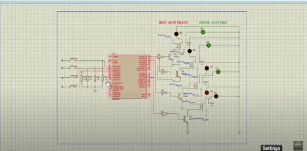
To begin, construct the project by pressing the F7 key and accessing the code file stored on your computer. As depicted in the image below, the setup includes four 10k ohm resistors, four switches, green LEDs (representing Free Slots), red LEDs (indicating Filled Slots), and a single relay.
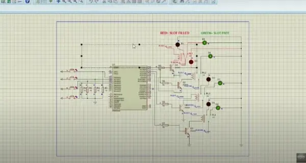
Suppose there are four vacant parking spaces, and a vehicle occupies slot D1. Upon a car’s arrival in a parking spot, the sensor detects this action and transmits a value of 1. Consequently, the LED indicator shifts from green to red, indicating that the particular spot is now reserved.
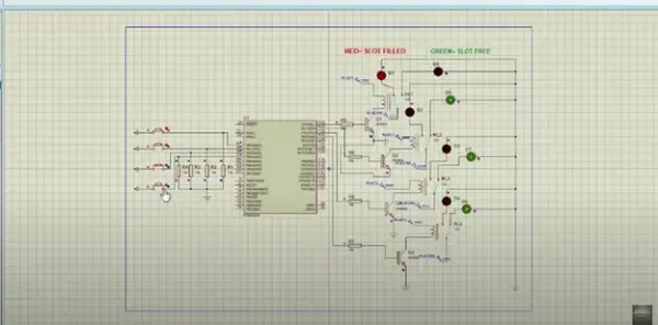
Moreover, upon a vehicle’s entry into slot D4, the sensor promptly detects its presence, causing the green light to switch off and the red light to illuminate. The relay functions as a switch: triggering the green light when the sensor output reads as 0. Conversely, when the sensor registers a value of 1, the relay engages, activating the red light to signal that the slot is reserved.
Video
Additionally, if you’re interested in executing the Automatic Car Parking System project using Atmega32, kindly refer to the video provided below.
Code
/*
Propose an Automatic Parking System. Whenever a car enters the parking area,
system display the available slots on I/O ports.
*/
.INCLUDE “M32DEF.INC”
CBI DDRA,0
CBI DDRA,1
CBI DDRA,2
CBI DDRA,3
SBI DDRC,0
SBI DDRC,1
SBI DDRC,2
SBI DDRC,3
PARKING1:
SBIS PINA,0
JMP PARKING2
SBI PORTC,0
CALL DelayMEGA
CBI PORTC,0
RJMP PARKING1
PARKING2:
SBIS PINA,1
JMP PARKING3
SBI PORTC,1
CALL DelayMEGA
CBI PORTC,1
RJMP PARKING2
PARKING3:
SBIS PINA,2
JMP PARKING4
SBI PORTC,2
CALL DelayMEGA
CBI PORTC,2
RJMP PARKING3
PARKING4:
SBIS PINA,3
JMP PARKING1
SBI PORTC,3
CALL DelayMEGA
CBI PORTC,3
RJMP PARKING4
DelayMEGA: // function used for delay
ldi R18,byte3(12* 1000 * 100 / 5)
ldi R17,high(12* 1000 * 100 / 5)
ldi R16,low(12* 1000 * 100 / 5)
subi R16,1
sbci R17,0
sbci R18,0
brcc pc-3
ret
- How does the system detect a vehicle?
The system uses sensors or switches connected to Atmega32 input pins to detect vehicle presence. - What indicates a free parking slot?
A green LED indicates a free parking slot. - What indicates an occupied parking slot?
A red LED indicates an occupied parking slot. - How are sensors or switches interfaced to the microcontroller?
Sensors or switches are connected to PORTA input pins of the Atmega32 and polled by the code. - How does the relay behave based on sensor output?
The relay is off (green LED active) when sensor output is 0 and engages (red LED active) when sensor output is 1. - Where is the project tested?
The project is tested in Proteus and coded in Atmel Studio using Atmega32. - What components drive the relay?
A 2N3904 transistor and a 12-volt DC supply are used to operate the relay. - How many parking slots are demonstrated in the simulation?
Four parking slots are demonstrated using four switches, four 10k resistors, and four pairs of LEDs.