Summary of ATmega328P Standalone Board
This article guides users in building a standalone ATmega328P board compatible with Arduino UNO, starting from a bare minimum configuration and evolving into the Cairoduino V1.0. It details essential components like voltage regulators, oscillators, and FTDI breakouts, explains PCB design using Eagle software via open-source files, and provides step-by-step instructions for burning the bootloader using an existing Arduino UNO as an ISP programmer.
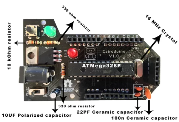
Parts used in the Cairoduino V1.0:
- ATmega328P chip
- L7805 voltage regulator
- 16MHz crystal oscillator
- 10 microfarad capacitor
- Two 22 picofarad capacitors
- DC power plug
- Reset button
- Power LED
- On/Off switch
- Pin headers
- FTDI breakout board
In this step-by-step tutorial we will learn how to build a standalone Arduino UNO compatible ATmega328p board.
ATmega328P Bare minimum configuration
Before building our standalone ATmega328P chip Arduino compatible board, let’s take a look at the awesome Arduino UNO board and see the main components that used to build that beautiful thing.
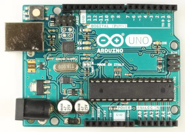
The first main component is the ATmega328P chip which is the brain of the board. A Voltage regulator that regulates the input voltage to a 5V clean output which gets used mainly by the ATmega320p chip. The 16MHz crystal oscillator, that creates an electric signal with a given frequency. Simply it counts the seconds so you don’t have to. Some LEDs to make you sure that the board is running smoothly and still alive. DC Plug allows you to connect the board to a DC power source. USB Port allows you to connect the board to your computer. Some pin headers to interface it with the external world (sensors, motors, LEDs,..) through some jumper wires.
After knowing the main components used in the Arduino UNO board, we can make one use the same main components that we stated before which called the ATmega328P bare minimum configuration.
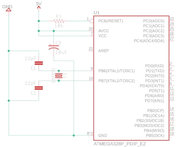
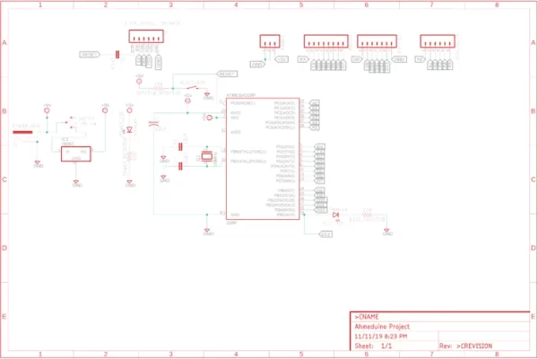
Schematic
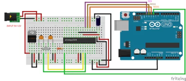
Wiring Diagram
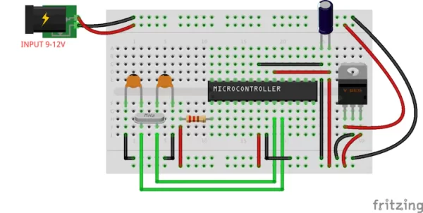
As you can see, the bare minimum configuration means using the smallest possible quantity of components that makes that thing runs without problems. But later on, we will add some more components like LEDs, buttons, pin headers,.. to spice things up.
The ATmega328P works at 5V that must be well regulated without any spikes that’s why we are using a 10microfarad capacitor between the 5V power line. In order to make the ATmega328p runs, you have to apply a HIGH logic value “5V” on the “reset” pin.
The “Reset” pin is an active low pin, which means if you applied a LOW logic value “0V” on it, it will restart the chip. So we keep it HIGH to make it disabled.
Usually, the ATmega328P chip works on a 16MHz crystal oscillator placed on the pins 9 and 10 but in order to make it oscillate it needs two 22Picofarad capacitors connected to the GND.
But we want to spice things up, let us add some more components to give the board more features and make it more user-friendly.
Schematic
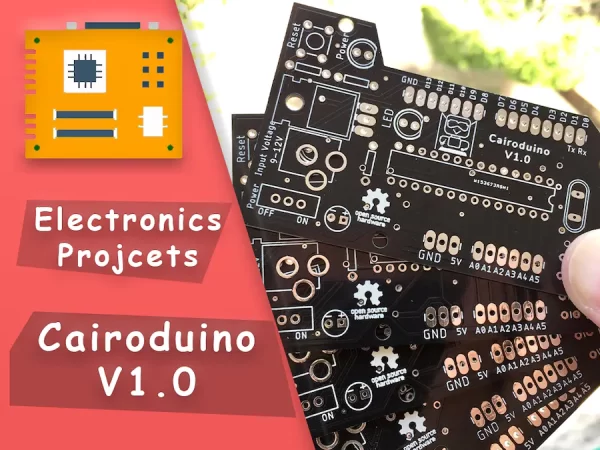
Cairoduino V1.0 Board
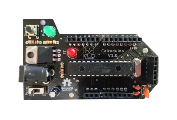
We added some new components to the bare minimum configuration that we discussed before to add more features to the board and make it more simple to use like a very normal Arduino UNO board.
- DC Power plug to make connecting the board to a power source easy and fast.
- L7805 voltage regulator, so you can plug it to any power source ranged between 7V-12V and the L7805 chip will regulate that voltage and give the ATmega328p chip a well-regulated 5V. The difference between the input voltage and the output voltage will go in a form of heat.
- Reset button, to be able to reset the board easily in case of any misbehaving.
- power LED as an indicator that tells the user if the board is connected to the power source or not.
- On&Off switch.
- pin headers to allow the user to connect any electronic components like sensors, LEDs, switches, … to the board easily using some jumpers, like any Arduino board.
- FTDI breakout board, to be able to connect the board to the laptop so you can program and upload the code to it easily without removing the ATmega chip itself.
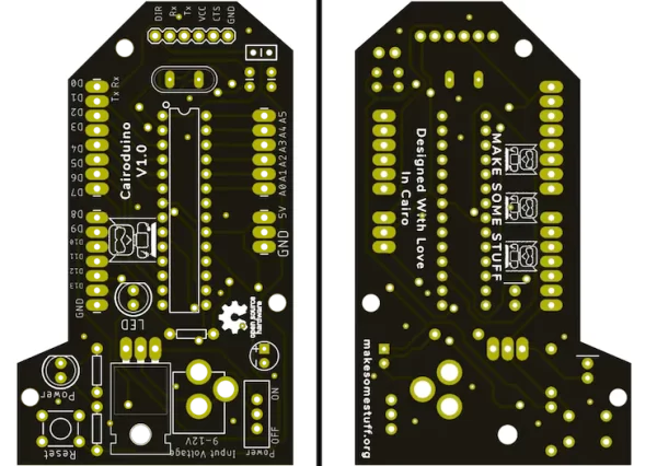
PCB Manufacturing
This board is designed on Eagle from Autodesk. You don’t have to be a PCB design expert to make or own this board. Because it’s fully open-source you can download the whole project from this link. Github
If you need this eagle project as a template so you can customize it according to your needs. You are very welcome to do anything you want to the project.
You can order your own Cairoduino board from PCBWay in just Two clicks. from this link. PCBWay
From my point of view, PCBWay has the most user-friendly web-based interaction design in the industry! You can instantly get the quotation of your PCB. You can also check the order fabrication and processing status online in your account panel. After your PCBs are sent out to your address, you can track your order shipping status online and a lot more.
Uploading the bootloader to the chip
To be able to use the Arduino IDE to program the chip. We need to burn the bootloader to the Atmega chip. At this step, we need an Arduino UNO board. We will use it as a programmer by connecting the MOSI, MISO, SCK pins between the ATmega328p chip and the Arduino UNO board.
If you already have an ATmega chip with the Arduino bootloader pre-loaded you don’t need to do that steps.
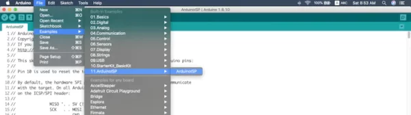
After connecting the ATmega chip with the Arduino board, we need to open the Arduino IDE –> File –> Examples –> ArduinoISP –> ArduinoISP
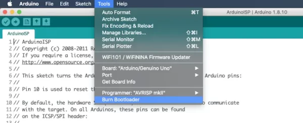
Then, set the Programmer to Arduino as ISP. Tools –> Programmer –> Arduino as ISP.
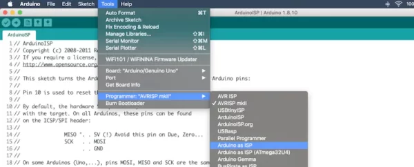
Now, it’s the time to burn the bootloader, Tools –> Burn Bootloader.
Source: ATmega328P Standalone Board
- What is the purpose of the L7805 voltage regulator?
The L7805 regulates input voltage ranging between 7V-12V to provide a well-regulated 5V output for the ATmega328p chip. - How do you reset the ATmega328P chip manually?
You can use the reset button on the board to restart it easily if it misbehaves. - Why are two 22picofarad capacitors needed?
These capacitors connect to the GND pins to allow the 16MHz crystal oscillator to function correctly. - Can I program the chip without removing the ATmega chip?
Yes, the FTDI breakout board allows connection to a laptop for programming without removing the chip. - What software was used to design the PCB?
The board was designed using Eagle software from Autodesk. - Where can I download the open-source project files?
The full project files are available on Github. - How do I burn the bootloader to the Atmega chip?
You must use an existing Arduino UNO board connected via MOSI, MISO, and SCK pins to act as an ISP programmer. - Which tool in Arduino IDE is used to burn the bootloader?
Select Tools –> Burn Bootloader after setting the Programmer to Arduino as ISP.