Summary of ATmega8 Based Smart Code Lock
This beginner project builds an ATmega8-based smart code lock with a 4x4 keypad, 16x2 LCD, PWM-controlled LCD backlight, relay output, and password-change and power-saving features. It includes schematics, BOM, PCB, firmware source files, AVR Studio project, and instructions for burning the provided HEX to the ATmega8.
Parts used in the ATmega8 Based Smart Code Lock:
- 330 ohm resistor (2 Nos) R3, R5
- 4k7 resistor (3 Nos) R2, R4, R6
- 200 ohm resistor R1
- 0.1uF ceramic disk capacitor (4 Nos) C1, C3, C4, C5
- 1N4007 diode (2 Nos) D1, D3
- LED 5mm any colour D4
- ATmega8L-8PU MCU U1
- 7805 voltage regulator U2
- Power connector 2 way CON1
- PCB mountable relay RL1
- On/Off switch SW1
- DC socket X1
- 16x2 LCD module LCD1
- 10K preset (blue plastic POT) RV1
- 28 pin narrow IC socket
- BC548 transistor (2 units) Q1, Q2
- Push buttons (16 units)
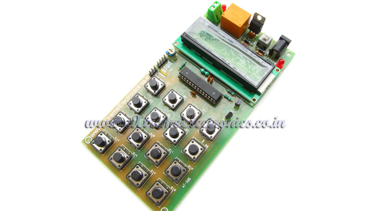
- ATmega8 based smart code lock PCB
Here is a project for beginners using Atmel AVR ATmega8. The project uses some techniques that are very useful for designers to learn and utilize.
- Alphanumeric LCD Module Interfacing.
- 4×4 Keypad interfacing.
- PWM Control of LED (Used to dim the back-light of LCD, like in some Nokia Phones)
- Basic Circuit design for AVR MCUs
- Connecting relays and other current demanding devices.
- AVR Studio and project management.
- compiling using free avr-gcc compiler.
- Using eXtreme Burner – AVR to burn hex code to AVR MCU.
NOTE:
Don’t waste time finding each part running from shop to shop. Get all the parts with exact specification in a ready to use kit! Purchase ATmega8 based smart code lock KIT.
Functions of the Project.
This device can be used to code protect any electrical device (like an electronic door, lock or safe). The user must enter a correct password to gain access. The password is entered using the built in 4×4 keypad matrix. The main LCD Module is used to display messages to the user. As soon as correct password is entered the relay is activated. This is indicated by a LED which is placed near the relay. The relay remains on as long as the user wishes. You just need to press a key to deactivate the relay.
After typing four digit password you must press the “OK” button (S8). At anytime you may press the “Cancel” key (S12 )to clear the input (e.g. when you enter any incorrect digit)
The smart code lock has the feature to change the password too. For this enter a special password which is ‘0000’, as soon as the system receives this special password it switches to change password mode. Here you need to enter the old password to gain permission, then enter the new password.
The smart code lock also support power saving feature. The backlight of LCD turns off automatically when the system is idle for few seconds. The cool thing about this is that it uses PWM to control the brightness of LCD Backlight. So the dimming is very smooth and it is like those used in many mobile phones.
Making it yourself!
You can fabricate the circuit on any general purpose PCB or breadboard. The schematic and the BOM (Bill of Material is given below). To save you from lots of trouble we have made a quality PCB of the same! If you purchase the PCB, you just need to solder different components at their proper place on the PCB and you are ready to go.
Burn the HEX file (given at the end of article) to the ATmega8 MCU using any suitable programmer and plug it into the 28 PIN IC Socket.
After assembling the circuit power it on using a 12V 500ma Center Positive DC Wall adaptor (you can use one that is used for mini TVs or Game Consols or Your DSL Modem). Adjust the variable resistor RV1 (just below the LCD module, on the left side, yes the blue thing!) until the LCD Shows some text.
Schematic for ATmega8 based Smart Code Lock

Bill of Materials (BOM)
|
Part List
|
||
| 01 | 330 ohm resistor (2 Nos) | R3, R5 |
| 02 | 4k7 Resistor (3 Nos) | R2, R4, R6 |
| 03 | 200 Ohm Resistor | R1 |
| 04 | 0.1uF Ceramic Disk Capacitor (4 Nos) | C1, C3, C4, C5 |
| 05 | 1N4007 Diode (2 Nos) | D1, D3 |
| 06 | LED 5mm Any Colour | D4 |
| 07 | ATmega8L-8PU General purpose 8 bit MCU | U1 |
| 08 | 7805 Voltage Regulator | U2 |
| 09 | Power Connector 2 Way | CON1 |
| 10 | PCB Mountable Relay | RL1 |
| 11 | On/Off Switch | SW1 |
| 12 | DC Socket | X1 |
| 13 | 16×2 LCD Module | LCD1 |
| 14 | 10K Preset (Blue Plastic POT) | RV1 |
| 15 | 28 PIN Narrow IC Socket | |
| 16 | BC548 Transistor(2 Units) | Q1, Q2 |
| 17 | Push Buttons (16 Units) | |
| 18 | ATmega8 Based Smart Code Lock PCB | |
Firmware Source Code
The firmware source code is written in a professional was that may seems confusing to a n00b programmer. The thing is that every piece of related functions are stored in a separate source files. That means the the project is composed of several ‘C’ source file. Each C file has set of related functions (like LCD Interfacing Routines or EEPROM Access). You must use AVR Studio as a project manager and WinAVR as compiler. Both the software must be installed in your PC. In the project folder their is a file with name “code_lock.aps”, this is the main AVR Studio Project file. Load it in AVR Studio. You can see the various files that are part of the project in the left hand pane as shown below. Double click any file to load in the editor. After a file has been loaded in editor you can view and change it.
For more detail: ATmega8 Based Smart Code Lock
- How is the password entered?
The password is entered using the built in 4x4 keypad matrix and after four digits you press the OK button (S8). - Can the input be cleared if a wrong digit is entered?
Yes, you can press the Cancel key (S12) at any time to clear the input. - How do you change the password?
Enter the special password 0000 to switch to change password mode, then enter the old password and then the new password. - What indicates the relay activation?
A LED placed near the relay indicates when the relay is activated. - How is the LCD backlight dimmed?
The backlight is dimmed smoothly using PWM control, and it turns off automatically when the system is idle for a few seconds. - What power supply is recommended?
Use a 12V 500mA center positive DC wall adapter as the power source. - How is the firmware programmed into the ATmega8?
Burn the provided HEX file to the ATmega8 MCU using any suitable programmer such as eXtreme Burner - AVR. - What development tools are needed to view or rebuild the source?
Use AVR Studio as project manager and WinAVR (avr-gcc) as the compiler to work with the C source files and project file code_lock.aps. - Can the circuit be built without the PCB?
Yes, the circuit can be fabricated on general purpose PCB or breadboard using the provided schematic and BOM.