Summary of ATmega8 Line Follower Robot (LFR) Project – Part 2/2
This article details the electronic assembly of a Line Follower Robot (LFR), focusing on the motor driver and microcontroller circuits. It explains how the L293D IC interfaces between the ATmega8 MCU and DC motors, enabling independent control via PWM signals. The text also outlines the specific pin configurations used for sensor inputs and motor outputs, noting that the control logic is implemented in C using AVR Studio 4.
Parts used in the LFR Project:
- L293D Motor Driver IC
- ATmega8 Microcontroller (MCU)
- DC Motors (M1 & M2)
- Infrared Sensor Cards
- AVR Studio 4 IDE
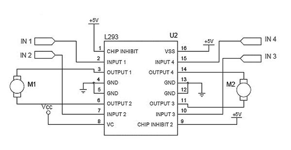
Now that the mechanical assembly part is over,and we have completed the construction of left and right (L&R) infrared sensor cards. Since the MCU (ATmega8) cannot drive the dc motors directly, a dedicated motor driver circuit is used. The motor driver circuit here is based on a simple 16-pin IC (L293D) which can drive two dc motors independently.
As can be seen in the circuit diagram, pins 4, 5, 13 and 12 of LM293 (U2) are connected to GND and the pin 16 (VSS) is connected to 5V. The ‘chip inhibit’ pins (1&9) act as the enable pins for the input-output pairs on left side and right side of the motor driver, respectively. Pin 8 (VC) receives the unregulated input supply (Vcc) from the LFR power supply circuit. It is noteworthy that this motor driver chip is PWM supporting, means that if you apply some voltage in the range 0V to 5V at any input, then it will be scaled up by a factor and will be available at the corresponding output.
The four input pins (2-7-10-15) receives motor drive instructions from the MCU. In short, U2 acts as the interface between the microcontroller (U3) and the dc motors (M1&M2) in which instructions from the microcontroller go into its input pins and the outputs are used to drive the robot motors.
LFR-Microcon-
troller Unit (MCU) Circuit Diagram
Here is the circuit of the MCU,wired around our favorite ATmega8 chip (U3). The first task is to resolve which pins of the MCU will be used for taking inputs from the infrared sensor cards and giving outputs to the motor driver circuit. As an exercise, I went for PC0 (left) and PC3 (right) of PORT C for the two inputs from two infrared sensor cards, and pins PB1 to PB4 of PORT B as outputs to motor driver circuit (actually only PB1 and PB4 are important at this time). The code is written using the C language so you need to be comfortable with the syntax of C language, concept of libraries, compiler, etc (IDE used is the AVR Studio 4). The final code (hex code) can be burned into the MCU using a suitable programmer (refer previous chapters of this avr tutorial).
Read More: ATmega8 Line Follower Robot (LFR) Project – Part 2/2
- Why is a dedicated motor driver circuit required?
The MCU cannot drive the DC motors directly. - Which IC is used for the motor driver circuit?
A simple 16-pin IC known as L293D is used. - How many DC motors can the L293D drive independently?
The chip can drive two DC motors independently. - What voltage is connected to pin 16 of the L293D?
Pin 16 is connected to 5V. - Which pins act as enable pins for the left and right sides?
Pins 1 and 9 act as the enable pins for the input-output pairs. - What type of signal does the motor driver chip support?
The chip supports PWM signals where input voltage is scaled up at the output. - Which MCU ports are used for infrared sensor inputs?
PC0 and PC3 of PORT C are used for the two sensor inputs. - Which MCU ports provide outputs to the motor driver?
Pins PB1 to PB4 of PORT B are used as outputs. - What programming language is used for the code?
The code is written using the C language. - Which IDE is recommended for compiling the code?
The IDE used is AVR Studio 4.