Summary of ATMEGA8 MOTORCYCLE ALARM CIRCUIT
This article describes an ATmega8-based motorcycle alarm circuit featuring a separate power supply and mobile phone call signaling. The system uses normally closed digital inputs that react to interruptions or short circuits, while analog inputs deactivate upon specific resistance changes. Multiple alarm contacts can be connected in series to enhance security coverage for motorcycles like the Honda Bol d'Or.
Parts used in the ATmega8 Motorcycle Alarm Circuit:
- ATmega8 microcontroller
- Digital alarm input (normally closed contact)
- Analog input with resistance detection
- Separate power supply
- Mobile phone calling module
- Series-connected alarm contacts
- Honda Bol d'Or mounting hardware
Separate power supply. Signalling on mobile phone call.This function has only a few hundred euros more expensive equipment. motorcycle into the phone by calling The digital alarm input is a normally closed contact. The… Electronics Projects, ATmega8 Motorcycle alarm circuit “atmega8 projects, avr project, microcontroller projects, “
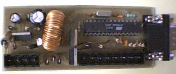
Separate power supply. Signalling on mobile phone call.This function has only a few hundred euros more expensive equipment.
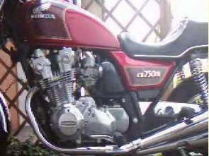
motorcycle into the phone by calling The digital alarm input is a normally closed contact. The analog input is deactivated when a certain resistance to +12 V is. It reacts to interruption and short-circuiting. Several alarm contacts can be connected in series. Help with mounting problems of the kind colleagues in the Honda Bol d’Or Board 🙂
motorcycle into the phone by calling The digital alarm input is a normally closed contact. The analog input is deactivated when a certain resistance to +12 V is. It reacts to interruption and short-circuiting. Several alarm contacts can be connected in series. Help with mounting problems of the kind colleagues in the Honda Bol d’Or Board 🙂
Source: ATMEGA8 MOTORCYCLE ALARM CIRCUIT Motorcycle alarm circuit alternative link: atmega8-p-ile-motosiklet-alarm.rar alternative link2 alternative link3
Alternative File Download LINK list (in TXT format): LINKS-2664.zip
- How does the digital alarm input function?
The digital alarm input is a normally closed contact that reacts to interruption and short-circuiting. - Can multiple alarm contacts be connected together?
Yes, several alarm contacts can be connected in series within this circuit design. - What happens when the analog input detects a specific resistance?
The analog input is deactivated when a certain resistance to +12 V is detected. - Does this project require expensive equipment for phone signaling?
No, the signaling on mobile phone call function costs only a few hundred euros more than standard equipment. - What type of power supply does this circuit use?
The circuit utilizes a separate power supply to operate effectively. - Is this project suitable for Honda Bol d'Or motorcycles?
Yes, the article mentions help with mounting problems specifically for colleagues in the Honda Bol d'Or Board. - What microcontroller is used in this alarm circuit?
The project uses the ATmega8 microcontroller as its core component.